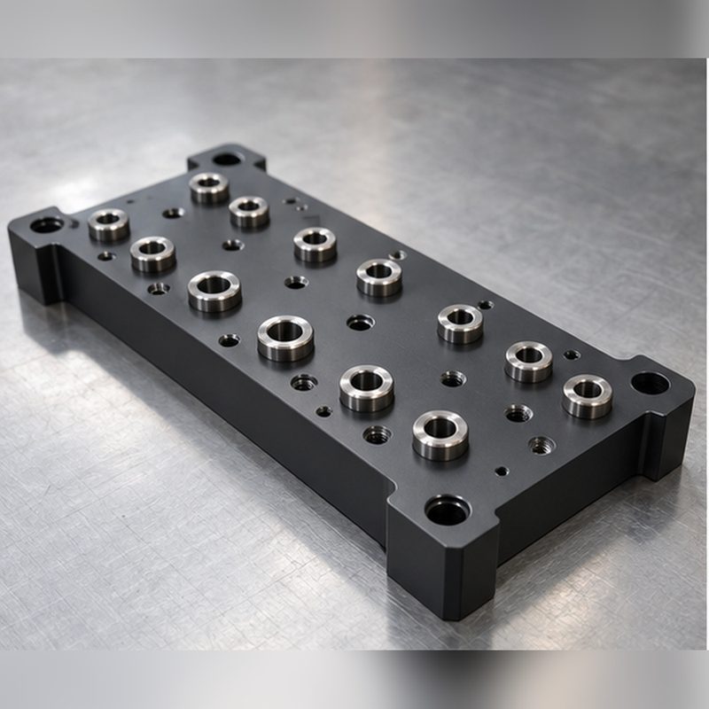
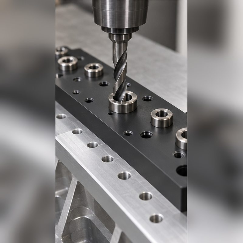
This drill jig carries a fixed hole pattern into an aerospace sub-assembly at a bench, with no machine tool involved. Hole position drives fastener fit and joint integrity, so the tool must place every hole in the same location on the first part and on the five-hundredth.
Project overview
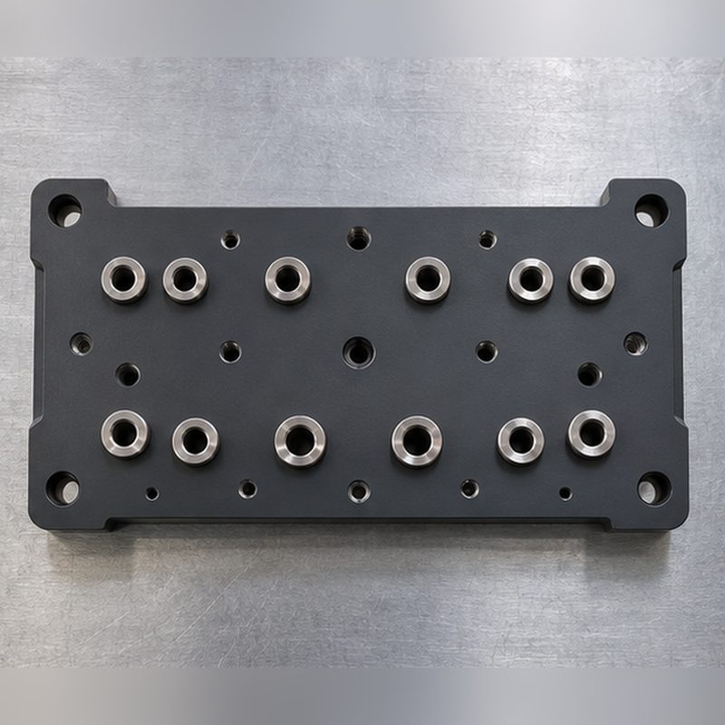
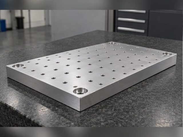
The fixture is a flat aluminium body with a machined locating face, press-fitted hardened drill bushings, and clamp or pin features that register the work against the tooling datums. It stays light enough for one person to handle, and the locating edges are relieved so only working surfaces carry contact.
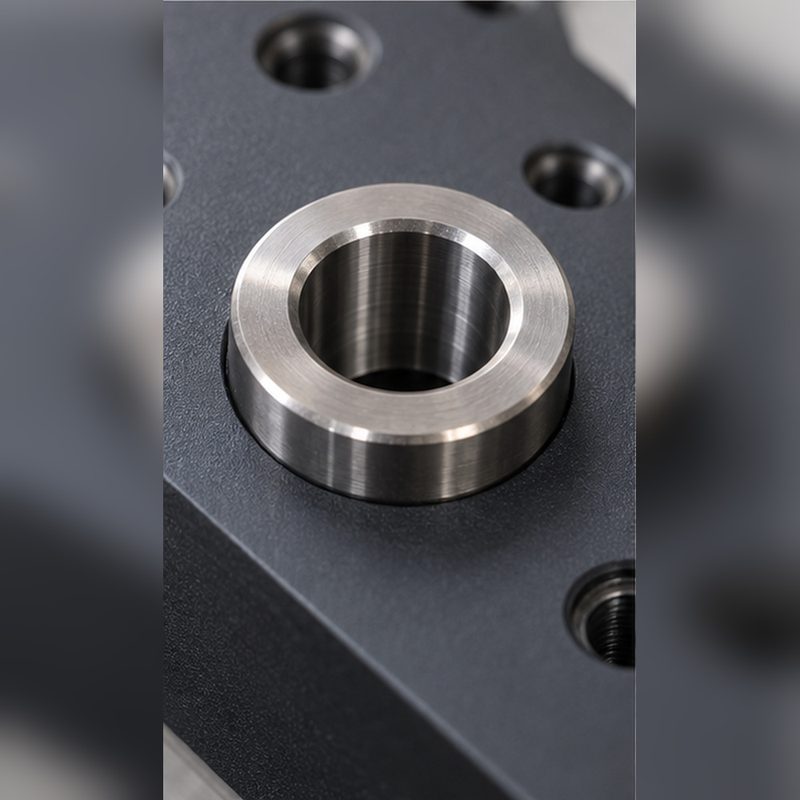
Two engineering points carry the tool. Bushing bores are located to a common datum rather than the plate outline, so the pattern stays correct even if the outside profile is cut slightly differently. And because drills chew up bare aluminium quickly — the bore loses size and the pattern drifts — the wear is moved into hardened replaceable steel bushings that press out and swap without scrapping the body. Fixture sizes and volumes below are typical for this kind of tooling, not one customer’s record, and no confidential program data appears in this study.
Project snapshot
| Item |
Detail |
| Industry |
Aerospace tooling / assembly |
| Part type |
Drill jig for a fixed hole pattern |
| Material |
2024-T351 or 7075-T651 aluminium plate |
| Finish |
Hardcoat anodize (Type III); bushing bores masked |
| Inserts |
Hardened, replaceable drill bushings |
| Volume |
Typically 1–5 fixtures per tooling program |
| Lead time |
Typically 7–12 working days plus finishing and bushing fit |
Technical specification
Values are shown as typical ranges for this class of fixture, not as a single customer’s measured drawing.
| Parameter |
Typical specification |
| Overall envelope |
Bushing edge typically 300–500 mm long, 20–30 mm thick |
| Minimum wall thickness |
5–8 mm around bushing bosses, 10 mm minimum to a datum edge |
| General tolerance |
±0.1 mm unless otherwise noted |
| Bushing bore position |
Typically ±0.02 mm true position, referenced to hard tooling datums |
| Bushing bore fit |
Press or slip fit matched to the supplied bushing OD |
| Locating-face flatness |
0.05 mm across the seating face |
| As-machined roughness |
Ra 1.6 µm on the locating face, Ra 3.2 µm on the body |
| Bushing bore hardness |
Hardened steel inserts, replaceable in service |
Engineering challenges
Pattern accuracy over the tool life. Any error in the bushing grid is multiplied by every part made on it, and the risk is stacking setup error — each re-fixturing adding displacement. The body is machined from one datum scheme: the locating face and datum edges are finished before any bushing bore is touched, and all bore positions come off that reference.
Wear concentrated in the bushings. Drills running at production rates wear an aluminium bore faster than a steel one. Rather than hardening the whole body or accepting gradual drift, hardened bushes go in every working position, converting a scrapped fixture into a consumable: the bushings swap and the body’s datum geometry is untouched.
Stability of a long, thin tooling plate. A fixture that is handled, clamped and stored cannot creep or warp. Stress-relieved stock is used, material is removed evenly from both sides, and hardcoat anodize on the handling surfaces keeps edges from mushrooming where the tool is set down.
Engineering decision
The main decision is where the accuracy lives. It goes in the body and the bushing seat, not the drill — the tool is what makes the pattern repeatable on a bench with no machine tool. That drives material and process: 2024-T351 gives higher strength and stability than a general-purpose alloy where ±0.02 mm true position must hold across a 400 mm bushing line, and 7075-T651 is used where the drawing calls for maximum stiffness in a thinner section. MIC-6 cast plate is substituted where the drawing prioritises flatness over strength, since stress-relieved cast stock moves far less after pocketing.
Because the fixture is a one-off plate with a specific outline, pockets and hand-holds, the body is machined from stress-relieved plate rather than produced as a formed section. On finishing the sequence is always machining → deburr → mask bushing bores → hardcoat → fit bushes, so neither the coating nor the bushing press disturbs the position just verified. Chem film replaces hardcoat where conductivity or a thinner coating is needed.
Manufacturing process
Step 1: Engineering review. Datum scheme, bushing fits, positional tolerance and finishing split are confirmed, and any conflict between the bushing standard and the drawing is raised.
Step 2: Stock preparation. The body is sawn oversize and squared from stress-relieved plate, with a relief step before finishing.
Step 3: Datum finishing. The locating face and hard tooling datums are finished first and used as the reference for later operations.
Step 4: Pocketing and bushing bore machining. Clamp pockets, lightening cut-outs and the bore pattern are machined from that reference, with bores sized to the supplied bushing fit.
Step 5: Masking and finishing. Edges are deburred, bushing bores are masked, and hardcoat anodize is applied to the wear and handling surfaces.
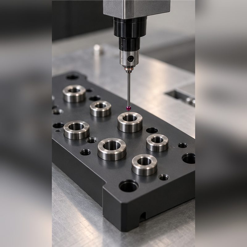
Step 6: Bushing fit and inspection. Hardened bushings are pressed or slipped into place, then the bore grid is mapped on a CMM and the position report issued with the tool.
Inspection methods
CMM positional report. Every bushing position is mapped against the tooling datums and reported as a true-position value, so the tool ships with a position record.
Bushing fit verification. Bore diameters are checked before finishing and after bushing installation to confirm the fit was not altered by coating growth.
First article inspection. A full FAI record covers datum features, bushing positions, fit condition and material certification; ongoing sampling follows the level the program specifies.
Surface finishing
Hardcoat anodize (Type III). A hard, wear-resistant layer on the body so handling does not damage the datum edges.
Masked bushing bores. Bushing bores are masked so coating growth does not disturb the press or slip fit of the hardened inserts.
Chem film option. Where conductivity or a minimal-thickness coating is required, chem film can replace hardcoat on those features.
Typical application
This tool is used where a hole pattern must be reproduced on an assembly line without a machine tool, and where a drifting pattern means rework on expensive structure. Aluminium with hardened inserts keeps the fixture light enough to handle all shift while resisting drill wear, and the documented position report makes it verifiable at each re-certification interval.
- Aerospace jig-led drilling where hole position drives fastener fit
- Bench work that must match a machine-tooled pattern
- Tooling programs needing documented, replaceable-bushing tooling
Explore the engineering
Have a similar part?
Upload the fixture drawing and bushing specification, and Chengdacai will review the datum scheme, bore fits, masking plan and material thickness before quoting.
Upload CAD for Quote

 Aerospace & tooling