
Aluminum Instrument Enclosure — Extruded 6063-T5 Housing with EMI Grounding
A two-piece enclosure for benchtop and rack-mounted instrument electronics, built on a custom extruded body profile with a CNC-machined lid. The design holds a 1.5 mm wall across a roughly 180 mm length, keeps connector positions to ±0.02 mm, and preserves conductive grounding pads after black anodizing.
Published October 16, 2026 · 6 min read
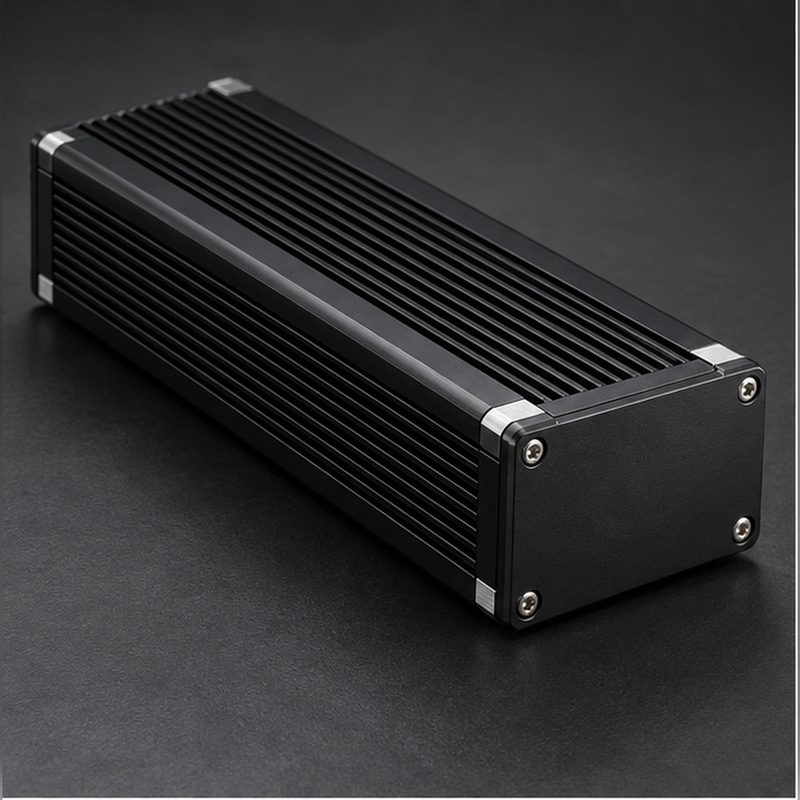
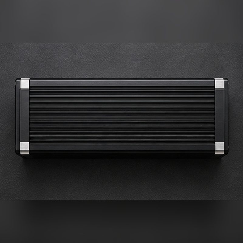
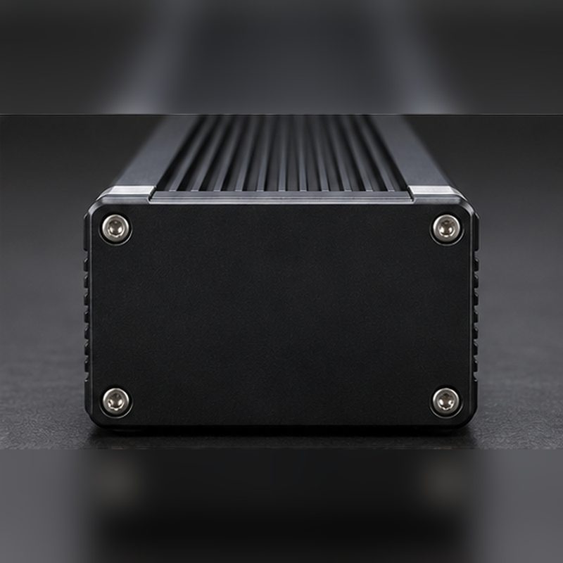
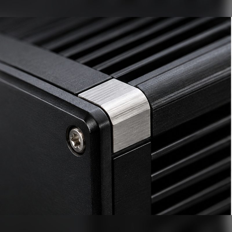
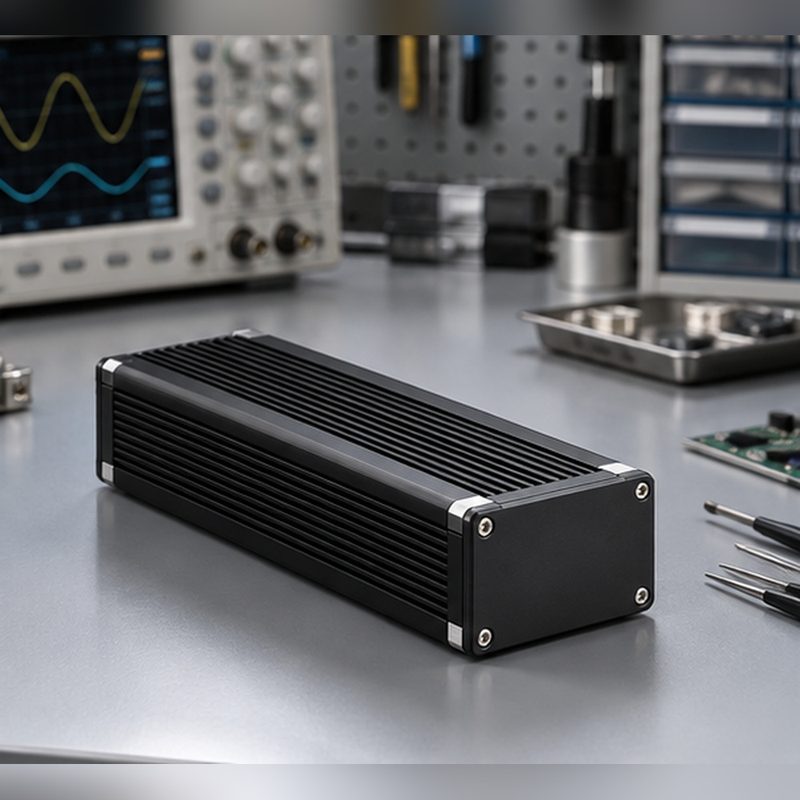
A two-piece enclosure for benchtop and rack-mounted instrument electronics, built on a custom extruded body profile with a CNC-machined lid. The design holds a 1.5 mm wall across a roughly 180 mm length, keeps connector positions to ±0.02 mm, and preserves conductive grounding pads after black anodizing.
Project overview
This part is a two-piece aluminum housing for instrument electronics. The body carries the PCB on internal standoff rails and closes with a matching lid that seats on a machined sealing land and a captive screw pattern. It began as a single prototype for design validation and continued into low-volume production on the same routing, so the fixtures, the die and the inspection plan did not have to be rebuilt between the two phases.
The body starts as a custom extruded profile rather than a solid billet. A die forms the pocket, the 1.5 mm side walls and the internal standoff rails in one continuous pass, which means wall thickness stays uniform over the full length instead of drifting with tool wear and cutter deflection. What the extrusion cannot produce — the connector cutouts, the lid sealing land, the screw bosses and the grounding pad geometry — is machined afterwards.
That split is where the engineering effort went. Deep pockets in a machined billet leave tall, thin walls that spring once the surrounding material is gone; an extruded profile arrives with those walls already supported along their length, so the material removal step becomes a finishing operation rather than a bulk clearing one. The remaining risk sits in the reference chain, because features cut on the extrusion’s end faces and features cut on its length have to agree with each other.
Dimensions, tolerances and quantities in this page are given as typical ranges for this class of part rather than one customer’s production record. The customer is not named, and the engineering approach shown here is representative of the instrument enclosures we run.
Project snapshot
| Item | Detail |
|---|---|
| Industry | Industrial electronics and instrumentation |
| Part type | Two-piece machined enclosure on an extruded body |
| Material | 6063-T5 extruded body, 6061-T6 machined lid |
| Finish | Black anodize (Type II), masked chem-film grounding pads |
| Volume | Prototype through low-volume production, typically 20–300 pieces |
| Lead time | Typically 7–12 working days after drawing approval |
Technical specification
Typical values for this class of instrument enclosure. Confirm against your own drawing before tooling is released.
| Parameter | Typical specification |
|---|---|
| Overall envelope | Typically 160–200 x 110–140 x 40–55 mm |
| Minimum wall thickness | 1.5 mm nominal, 1.0 mm in local ribs |
| General tolerance | ±0.05 mm (ISO 2768-f unless noted on the drawing) |
| Connector and mounting positions | ±0.02 mm within a single setup |
| Sealing face flatness | 0.05 mm over 100 mm on the lid land |
| Surface finish, as machined | Ra 1.6 µm on cosmetic exterior faces |
| Profile wall consistency | Within 0.10 mm along the extruded length |
Engineering challenges
Holding thin walls over a long body
A pocketed enclosure with 1.5 mm walls is the classic case where a part moves after machining. Extruding the body first means the wall is formed by the die and supported continuously along its length, and the finishing passes only have to blend the machined areas into it rather than create it.
Keeping grounding pads conductive after anodizing
Anodize is an insulator, which is a problem for a housing that also has to bond electrically for EMI. The grounding pads and the lid contact ring were defined as masked zones during the quoting stage, not added afterwards, so the chem-film coating and the anodize line could be sequenced without a second masking operation on a completed part.
Aligning features across faces
Connector cutouts, the lid screw pattern and the internal standoff rails all reference one another. Machining the critical features in a single 5-axis setup, off the extruded profile’s datum faces, kept them aligned instead of stacking setup error from part to part.
Engineering decision
Extruding the body before machining was the decision that shaped everything else. For a hollow enclosure of this length, a die amortises quickly at low-volume production quantities: it removes the bulk material clearing that a billet approach requires, keeps wall thickness consistent by forming rather than cutting, and shortens cycle time on every part after the first. The body runs in 6063-T5 because that alloy extrudes cleanly, takes a uniform anodized finish and holds the required flatness on the sealing land; the lid runs in 6061-T6 because it is a flat plate with screw and sealing features that benefit from higher strength and needs no die. Finishing was sequenced rather than appended: mask and chem-film the grounding zones, anodize the visible surfaces, laser mark the identification, so no operation reopens a coated face.
Manufacturing process
Step 1: Engineering review
Wall thickness, corner radii and boss engagement are checked against the drawing, and the zones that must stay conductive are identified before the die is quoted.
Step 2: Profile and die design
The extrusion cross-section is developed around the PCB envelope, standoff rails and screw bosses, with wall thickness and corner radii set so the die can run at a stable rate.
Step 3: Extrusion and cut to length
The body profile is extruded in 6063-T5 and cut to rough length with allowance for facing and cleanup on both ends.
Step 4: CNC machining
End faces, connector cutouts, the lid sealing land and the screw bosses are machined, with the critical features grouped into one 5-axis setup to preserve their relationship.
Step 5: Deburr and masking
Edges are broken and the parts cleaned, then the grounding pads and lid contact ring are masked ahead of finishing.
Step 6: Finishing and final inspection
Black anodize on the exposed surfaces, chem-film on the masked zones, then dimensional and cosmetic sign-off before packing.
Inspection methods
First article inspection
A full dimensional FAI is run against the drawing on the first part, with a report available to the customer. Acceptance values follow the drawing and the customer’s own requirements.
In-process CMM checks
Connector positions, screw boss locations and pocket depths are verified on a CMM during the run rather than only at the end, so a drift is caught while the setup is still live.
Fit and finish review
Lid-to-body fit, screw engagement and the cosmetic faces are reviewed under standard lighting before packing, including a continuity check on the masked grounding zones.
Surface finishing
Black anodize (Type II)
An even matte black exterior for a finished instrument appearance and corrosion protection, applied over a light bead blast so the machined and extruded areas read as one surface.
Masked chem-film pads
Grounding pads and the lid contact ring are kept electrically conductive for EMI bonding. The coating class and any customer specification should be confirmed against the drawing before production.
Laser-marked identification
Part number and connector labels are laser marked after anodizing, so there are no inks or adhesive labels to wear off in service.
Typical application
Enclosures of this type suit electronics programmes where casting tooling is not justified but wall precision, sealing and EMI performance still matter — instruments, controllers and sensor electronics released in the tens to hundreds of units.
- Instrument and analyser housings where a consistent exterior finish matters as much as the internal fit.
- Controller and sensor electronics that need a defined grounding path alongside a protective coating.
- Programmes that start with a prototype and continue into recurring batches on the same tooling and routing.
Explore the engineering
- Aluminum extrusion capabilities — profile design, die development and extrusion tolerances.
- CNC machining of extruded profiles — how machined features are referenced off an extruded datum.
- 6063 aluminum — extrusion behaviour, strength and finishing characteristics.
- Anodizing and chem film — masking strategies for parts that must stay conductive.
- Electronics enclosure projects — more housings and frames for this sector.
Have a similar part?
Send the drawing with the alloy, finish and tolerance notes, or upload the CAD model directly. We review manufacturability and the extrusion-versus-machining trade-off before quoting, not after the parts are on the machine.
Material data for the alloys in this article
Composition, temper options, mechanical properties and selection notes for each grade discussed above.
Thank you — your RFQ has been received.
Our engineering team will review your drawing and reply within one business day. A confirmation has been sent to your email.
Need to reach us sooner? WhatsApp +86 15119686849 · chloe@chengdacai.com