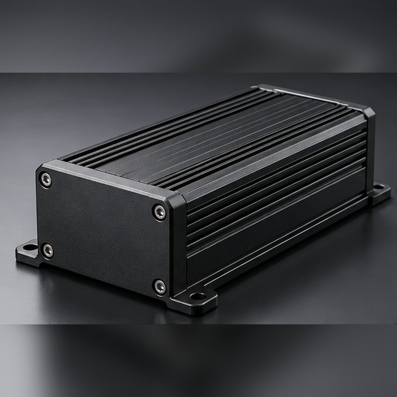
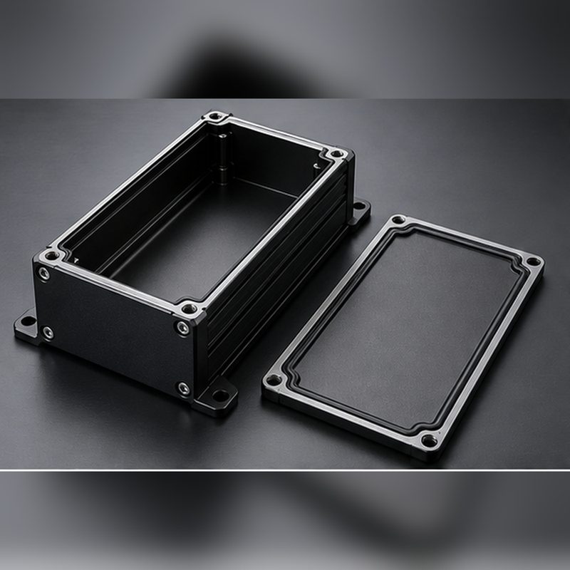
A two-part sealed enclosure: a hollow extruded body with an internal cavity and a removable lid that clamps onto a CNC-machined O-ring gland — built for machine-mounted control electronics exposed to vibration, coolant mist and repeated service access.
Project overview
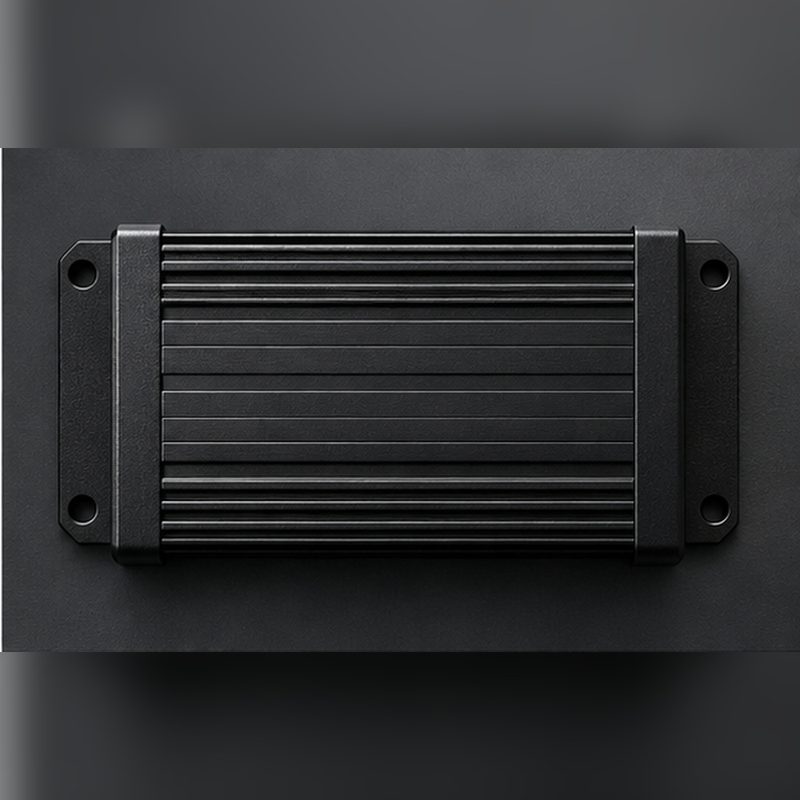
This project is a sealed control module enclosure. The body is a hollow aluminum profile with an internal cavity, mounting feet, connector cut-outs and service bosses; the lid is a machined plate that closes onto a machined O-ring gland running around the perimeter. The enclosure lives on machinery, so it has to keep coolant and dust away from the electronics, hold up to continuous vibration, and still open cleanly every time a technician services the module.
Rather than milling the body from a solid billet, the repeating cross-section was designed as a custom die and extruded in 6063-T5. The extruded length is cut to size, and every sealing and locating feature — land, gland, bores, thread bosses and end faces — is added afterwards by CNC. The lid is milled from 6061-T6 plate, which is stronger than the extrusion alloy and needs only single-setup face work.
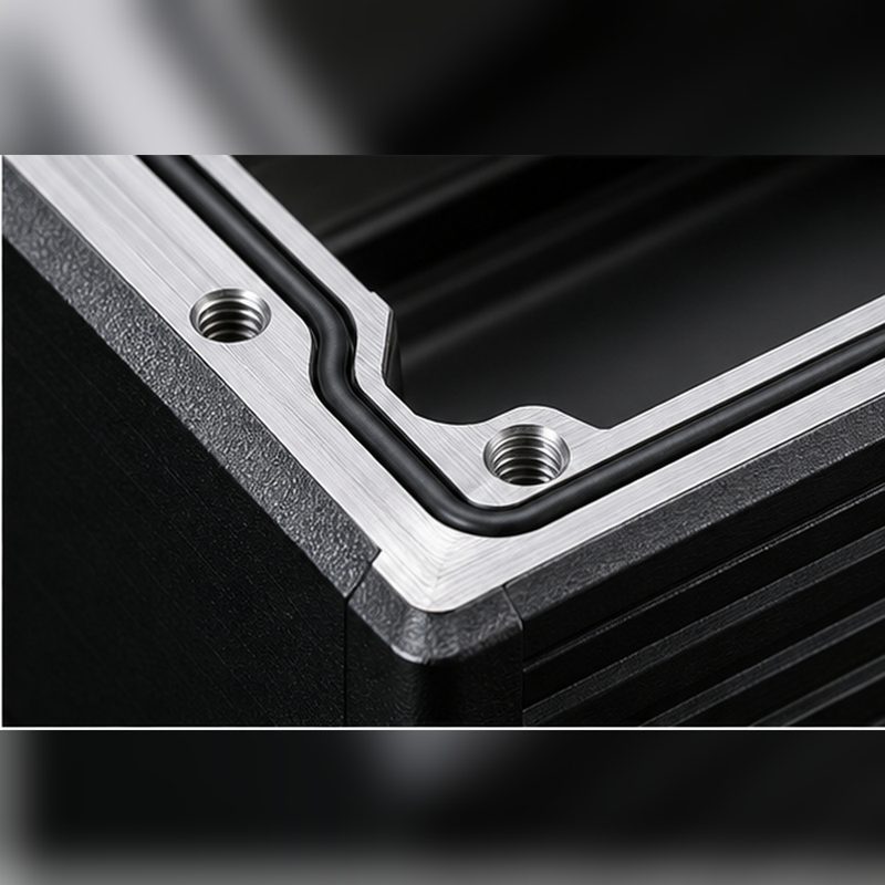
The part revolves around the sealing land. It has to stay flat after the profile is cut, faced and pocketed, and the gland has to follow the seal supplier’s gland table rather than an invented cross-section. Roughing and finishing are separated so the sealing land and gland are cut last, once the material has settled. Service bosses receive helical inserts so the threads survive repeated opening. Every dimension, sealing class, volume and lead time on this page is shown as a typical range for this class of enclosure rather than one customer’s production record; the extrusion choice, sealing strategy and finishing sequence are representative of the sealed housings we build.
Project snapshot
| Item |
Detail |
| Industry |
Industrial equipment / machine controls |
| Part type |
Sealed two-part enclosure with removable lid |
| Material |
6063-T5 extruded body, 6061-T6 machined lid |
| Finish |
Bead blast + black anodize (Type II), sealing faces masked |
| Volume |
Typically 20–300 pieces for prototype and low-volume builds, 50–500 pieces in recurring batches |
| Lead time |
Typically 7–12 working days for machined prototypes, plus typically 3–5 weeks for a new extrusion die |
Technical specification
The values below describe what is typical for sealed extruded enclosures of this size. They are planning ranges for the class of part, not the released drawing of any one program.
| Parameter |
Typical specification |
| Overall envelope |
Typically 150–200 x 90–120 x 50–70 mm |
| Profile wall thickness |
Typically 2.0–2.5 mm nominal through the cavity walls |
| As-extruded profile tolerance |
Typically ±0.25 mm on outside dimensions before machining |
| Minimum machined wall |
Typically 1.5 mm after facing and pocketing |
| Sealing land flatness |
Typically 0.05 mm over 100 mm after final facing |
| O-ring gland |
Machined to the seal supplier’s gland table; width and depth per the seal specification |
| Thread engagement |
Typically 1.5 x D tapped bosses, with helical inserts at serviced threads |
| General tolerance |
Typically ±0.05 mm on machined features unless the drawing states otherwise |
Engineering challenges
A seal that repeats from the first article
An enclosure only seals if the gland cross-section and the land flatness are right on the first part. Groove width and depth are taken from the seal supplier’s gland table and machined to that table, so O-ring compression is defined by the seal rather than by a shop habit.
Keeping the land flat after cut, face and pocket
An extruded profile arrives with its own straightness and twist, and pocketing releases more of it. Stock is left on the sealing faces at extrusion, the profile is faced in one setup to control squareness, and the land is finished last so it holds 0.05 mm over 100 mm.
Threads that survive being opened
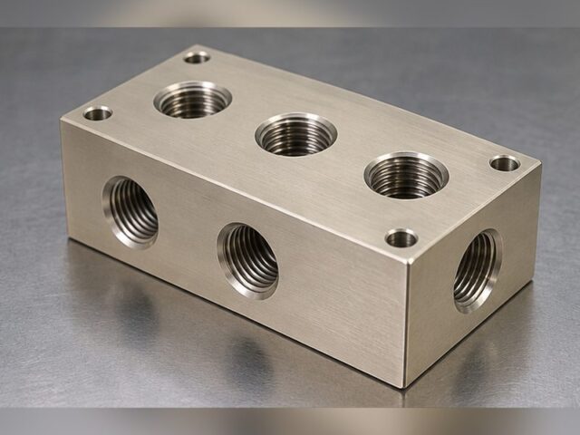
A 2.0–2.5 mm extruded wall cannot carry a reliable machine screw on its own, so the die thickens the corner sections into bosses and the machined pads are drilled and tapped there. Serviceable locations take helical inserts for repeated fastening.
Engineering decision
Extruding rather than milling was driven by the cross-section: the cavity and its wall thickness repeat along the full length, so a die removes a large volume that a billet would have to cut away, and it holds wall consistency from part to part. 6063-T5 was chosen over 6061-T6 because its lower alloy content extrudes thin walls faster and produces the smoother surface an anodized cover needs; 6061-T6 is reserved for the lid, where stiffness matters more than extrudability. The seal-critical geometry deliberately stays out of the die: a die is costly and has a long lead time, so the gland is machined after cut-to-length, which lets the groove follow the seal table and be corrected later without re-cutting tooling. Bead blasting then black anodizing gives a uniform industrial appearance and corrosion protection, and the sealing land and gland are masked so coating growth cannot change the gland fit.
Manufacturing process
Step 1: Profile and die engineering
The cross-section, wall thickness, corner radii and boss locations are reviewed against the drawing before the die is cut, with stock allowance added to the faces that will be machined.
Step 2: Extrusion and aging
The profile is extruded in 6063 to the T5 temper, then quenched, stretched and straightened so the cut lengths are straight enough for machining.
Step 3: Cut to length
Extruded lengths are cut to finished length plus facing allowance, and the ends are prepared for the first machining setup.
Step 4: CNC machining
The body is faced, pocketed and drilled; the sealing land, gland, connector cut-outs, bores and threaded bosses are machined, with sealing features cut after the bulk material is removed.
Step 5: Deburr, bead blast and masking
Edges are deburred, the body and lid are bead blasted for a uniform matte texture, and the sealing land and gland are masked.
Step 6: Anodize and final inspection
Black anodize (Type II) is applied, masking is removed, and the enclosure is dimensionally checked and closed for a seal fit sign-off.
Inspection methods
Gland and land verification
Gland width, depth and sealing land flatness are checked against the seal specification on a CMM after final machining.
First article inspection
A full first article inspection report is produced on the first part, with in-process sampling on the run at the sampling level agreed with the customer.
Seal fit check
Lid-to-body closure and O-ring compression are confirmed on an assembled sample before the finish is signed off, so a gap or an over-compressed seal is caught before anodizing.
Surface finishing
Bead blasting
A uniform matte pre-texture that blends tool marks across the extruded and machined surfaces so the anodized finish looks consistent.
Black anodize (Type II)
Corrosion protection and a clean industrial appearance for a controller body that sees coolant, mist and handling.
Masked sealing surfaces
Sealing lands, gland walls and thread crests are masked so anodize growth does not change gland fit or thread engagement.
Typical application
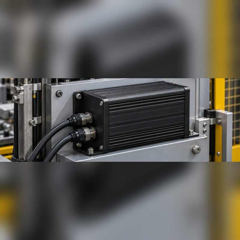
Enclosures like this house drives, controllers and junction electronics that live on industrial machinery, where the electronics must stay dry while remaining reachable for service. Extruding the repeating section and machining only the sealing features keeps unit cost sensible at low volume without the tooling commitment of a casting.
- Machine-mounted control modules and driver housings
- Junction boxes on coolant- or mist-exposed production equipment
- Field enclosures opened routinely for maintenance or firmware access
Explore the engineering
Have a similar part?
Send the CAD model and drawing with the alloy, sealing requirement and finish callout, and our engineering team reviews the profile, wall thickness, gland and tolerances for manufacturability before any quotation is issued. You get an engineering response first, then a quote that reflects the route we actually intend to run.
Upload CAD for Quote

 Industrial equipment & controls