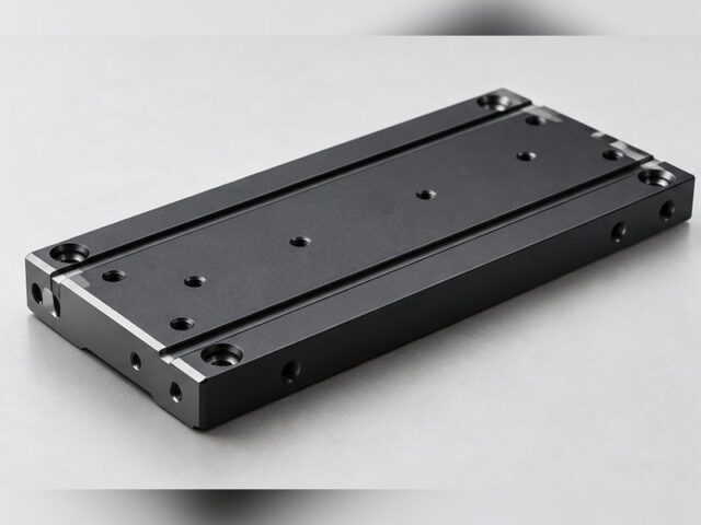
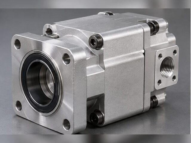
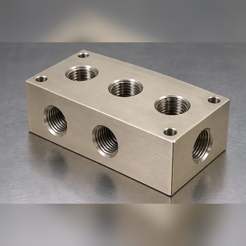
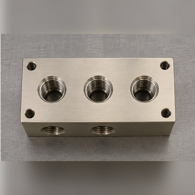
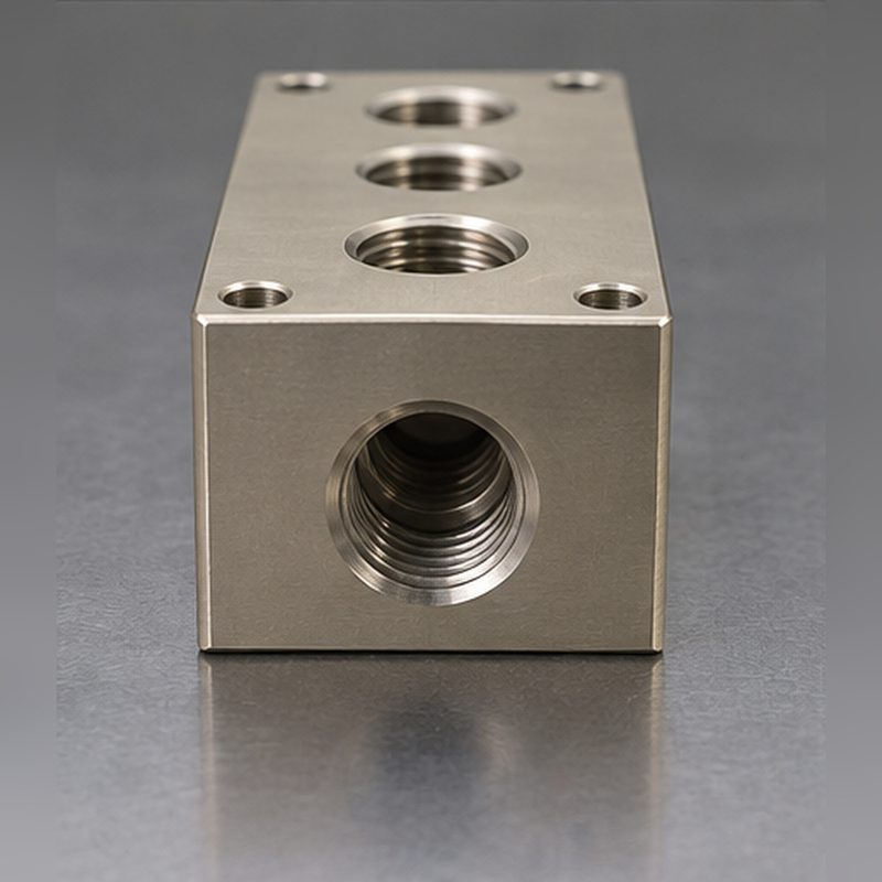
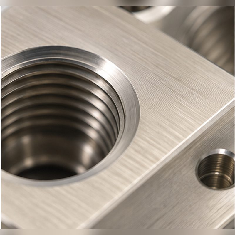
A pneumatic manifold machined from 6061-T6 aluminum: valves and fittings on the outside, a network of cross-drilled passages on the inside, sealed, leak tested and finished for machine air control.
Project overview
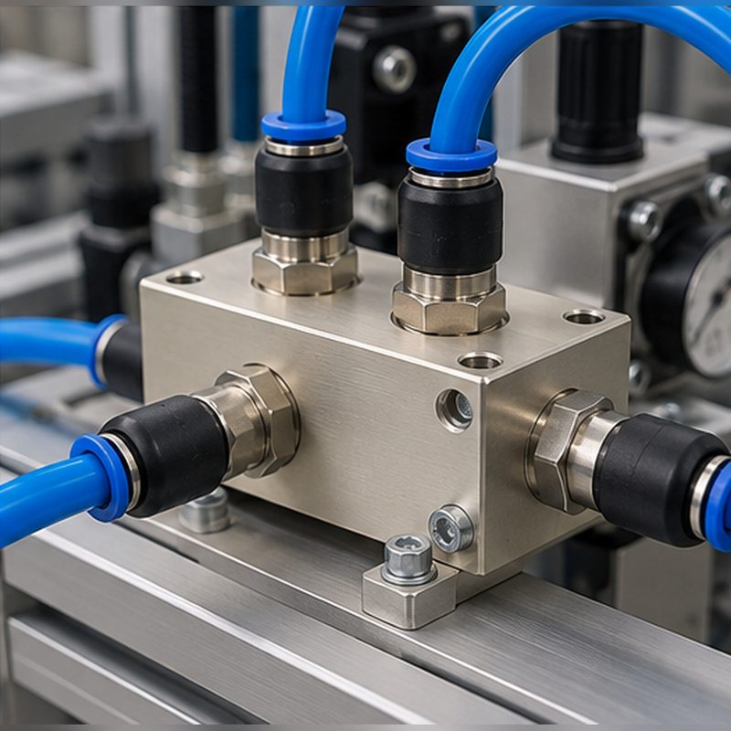
This project is a pneumatic manifold block. It is a solid aluminum body with valves and fittings mounted on its outside faces and a network of cross-drilled passages routing air through the inside. Consolidating that routing into one machined block replaces a nest of tubing and fittings with sealed internal passages that are more compact, easier to service and far less likely to be knocked loose.
The difficulty in a manifold is entirely internal. Passages are deep and they intersect, so bores are peck-drilled with controlled break-through to stay straight and to keep the drill from wandering into a neighbouring wall. Every cross-hole intersection is deburred internally rather than only at the surface, because a burr left inside will restrict flow or break free and travel into a valve. Valve-mount faces are finished flat so gaskets and O-rings seat evenly and actually seal.
The block is machined from milled plate and bar. Pressure-tightness depends on homogeneous material with no internal discontinuity anywhere in the pressure path, and the passages run in three directions at once — so the geometry is cut rather than formed. Before finishing, the block is pressure-tested with ports plugged to confirm there are no cross-leaks or porosity. All block sizes, port standards, test pressures, volumes and lead times are shown as typical ranges for this class of manifold rather than one customer’s record; the passage strategy, internal deburring and leak testing are representative of the manifolds we machine.
Project snapshot
| Item |
Detail |
| Industry |
Automation / industrial equipment |
| Part type |
Pneumatic control manifold block |
| Material |
6061-T6 aluminum plate and bar |
| Finish |
Chem film (chromate conversion coating), ports masked |
| Volume |
Typically 20–300 pieces for prototype and low-volume builds, 50–500 pieces in recurring batches |
| Lead time |
Typically 7–12 working days for machined and tested first articles |
Technical specification
The values below describe what is typical for a machined pneumatic manifold of this size. They are planning ranges for the class of part, not the released drawing of any one program.
| Parameter |
Typical specification |
| Block size |
Typically 120–180 x 50–80 x 35–50 mm |
| Port threads |
Standard G or NPT ports per the drawing |
| Passage diameter |
Typically 4–10 mm cross-drilled passages, deburred and flushed |
| Wall between passages |
Typically 3 mm minimum between adjacent and intersecting bores |
| Valve-mount face flatness |
Typically 0.05 mm over the sealing footprint |
| Leak test |
Typically 1.5 times working pressure, commonly 10–16 bar |
| Internal cleanliness |
Intersections deburred internally and passages flushed before assembly |
| General tolerance |
Typically ±0.05 mm on machined features unless the drawing states otherwise |
Engineering challenges
Deep passages that intersect
Air has to travel through the block along deep drilled bores that meet other bores at an angle. Peck drilling with controlled break-through keeps each passage straight, avoids drill walk into a thin wall, and keeps the intersection clean enough to flow properly.
Deburring the inside, not just the outside
Cross-hole intersections leave burrs exactly where they are hardest to reach. Intersections are deburred internally with the passages then flushed, so loose material cannot sit inside the block waiting to enter a valve or cylinder.
Sealing faces that stay flat
Valves and gaskets only seal against a flat, well-finished face. Valve-mount footprints are finished flat over the sealing area after the bulk of the block has been machined, so gaskets and O-rings compress evenly instead of bridging a low spot.
Engineering decision
The block is cut from plate and bar because a manifold is a pressure boundary first and a machined part second. Pressure-tightness depends on homogeneous material through the whole pressure path, with no internal discontinuity anywhere a passage runs; the layout also runs in three axes, so the block is cut rather than formed. 6061-T6 is the right alloy for the job: it machines cleanly, taps reliably for G and NPT ports, and holds the thin walls between adjacent bores without tearing. Chem film is chosen because it protects the aluminum and keeps the block electrically conductive without depositing measurable thickness inside threads or passages, and the pressure test is run before finishing, so a block that fails never consumes coating capacity or a finishing slot.
Manufacturing process
Step 1: Engineering review
Passage routing, port standards, wall thickness between bores and the test pressure are reviewed before quoting, with the drill approach for each deep passage planned in advance.
Step 2: Face and profile machining
The block is squared up from 6061-T6 stock and the valve-mount faces are roughed, leaving stock for the final flatness pass.
Step 3: Deep-hole drilling
Passages are peck-drilled with controlled break-through to keep bores straight and walls intact.
Step 4: Porting and tapping
Ports are drilled and tapped to the specified thread standard, with sealing faces finished flat in the same setup where possible.
Step 5: Internal deburring and cleaning
Cross-hole intersections are deburred internally and the block is flushed until passages are clean and free of chips.
Step 6: Leak test and finishing
Plugged ports are pressure-tested to confirm no cross-leaks or porosity, then chem film is applied and the block passes final inspection.
Inspection methods
Pressure and leak test
All passages are plugged and pressurised to confirm there are no cross-leaks or internal porosity; the test pressure follows the drawing and the customer’s own requirements.
Face flatness check
Valve-mount face flatness is verified over the sealing footprint before finishing, so any correction happens while there is still stock to remove.
First article inspection
A full first article inspection report covers port positions, thread gauging and passage verification, with in-process sampling on the run at the sampling level agreed with the customer.
Surface finishing
Chem film (chromate conversion coating)
Corrosion protection that leaves the block electrically conductive and adds no measurable thickness inside passages or port threads.
Masked ports and sealing faces
Threads and gasket faces are protected during finishing so port engagement and sealing behaviour are unchanged.
Clean and cap
Passages are flushed and ports capped for transport, so the inside of the block arrives free of chips and shop debris.
Typical application
Pneumatic manifolds like this consolidate valves, fittings and air routing into one machined block, replacing a nest of tubing with sealed internal passages that are more compact and easier to service. Chem film suits the application because it protects the aluminum without adding thickness inside threads and passages, and keeps the block conductive for grounding.
- Valve islands and air-control blocks on automation equipment
- Machine-mounted pneumatic distribution for cylinders and grippers
- Test rigs and fixtures that need repeatable, leak-free air routing
Explore the engineering
Have a similar part?
Send the CAD model and drawing with the port standards, passage sizes, test pressure and finish callout, and our engineering team reviews the passage routing, wall thickness between bores and the leak-test strategy before quoting. The manufacturability review comes first, so questions about drilling, deburring or testing are answered before the quote is issued.
Upload CAD for Quote

 Industrial equipment & controls