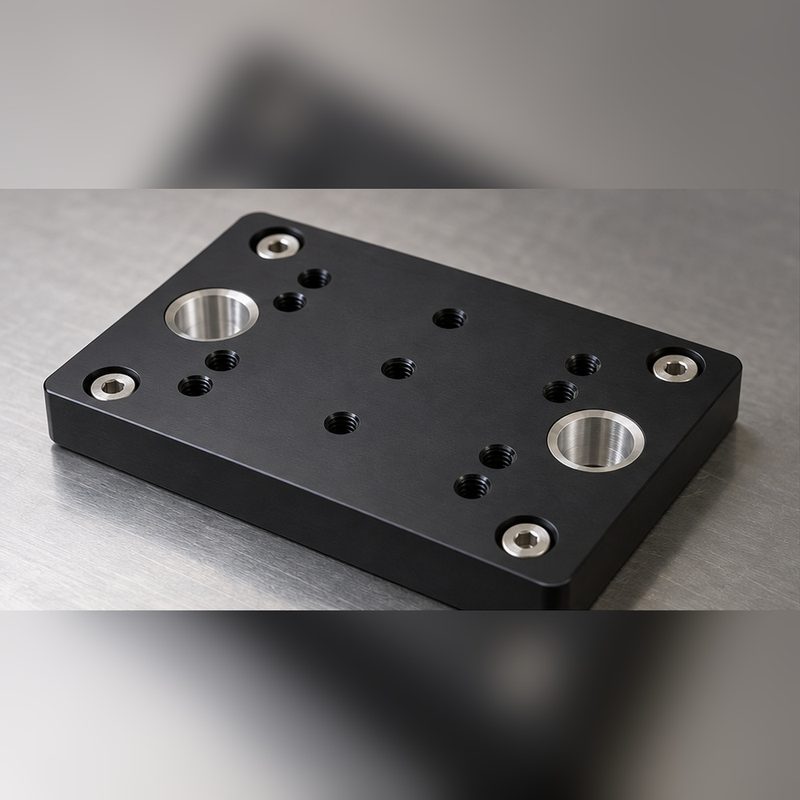
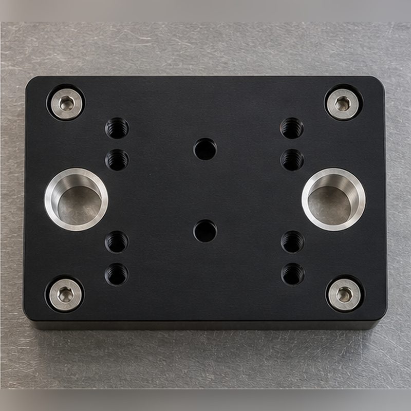
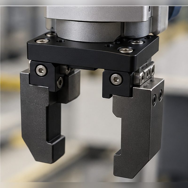
This baseplate is the mounting foundation that grippers, tool changers and sensors bolt onto at the end of a robot arm. It is taken on and off the tooling stack constantly, so the target is not one passing measurement — it is repeatable location and a wear surface that survives thousands of tool changes.
Project overview
The part is a thin, wide plate worked on two faces: a dowel location grid, sensor pockets, weight-relief slots and tapped mounting holes on top, and a machined register step on the underside that seats against the tool changer. Because so much of the plate is opened up for weight, stiffness comes from geometry rather than added material, so pocket walls keep a consistent section and inside corners get generous radii.
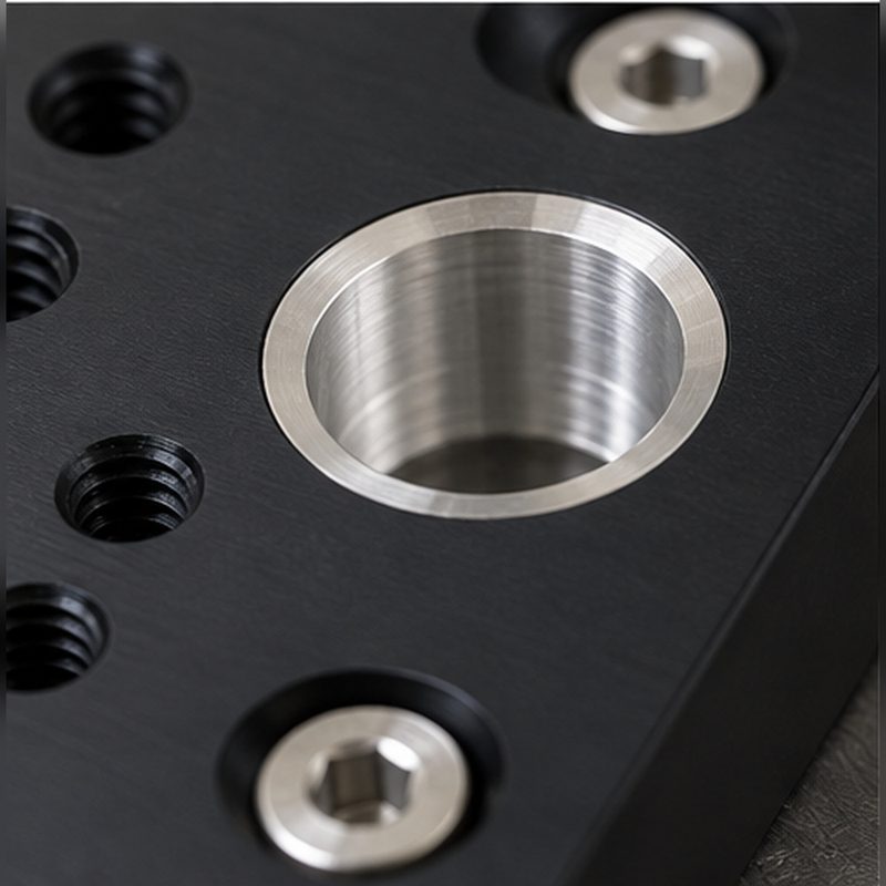
The dowel grid decides whether the whole tooling stack works. Every attachment references those bores, so they are reamed to an H7 fit and located to a common datum rather than from the plate edges. Bare aluminium bores would wear oval under repeated insert-and-remove cycles, so the running and contact surfaces are hardcoat anodized: the plate keeps aluminium’s weight and machinability while the wear faces behave closer to a much harder material.
Figures here are typical ranges for this class of tooling, not one customer’s production record, and no customer or contract detail is reproduced.
Project snapshot
| Item |
Detail |
| Industry |
Automation equipment / robotics |
| Part type |
End-of-arm tooling mounting baseplate |
| Material |
6061-T6 aluminium |
| Finish |
Hardcoat anodize (Type III), masked dowel bores |
| Volume |
Tooling and low-volume batches, typically 10–100 pcs |
| Lead time |
Typically 7–12 working days for a first article |
Technical specification
Typical ranges for this class of part, not a single customer’s drawn dimensions.
| Parameter |
Typical specification |
| Overall envelope |
Typically 180–250 × 110–150 × 12–20 mm |
| Minimum wall thickness |
3–5 mm at pocket walls and slot sections |
| General tolerance |
±0.1 mm unless otherwise noted |
| Dowel bore fit |
H7 reamed, located to a common datum |
| Hole-pattern position |
±0.02 mm true position |
| Tooling-face flatness |
0.05 mm across the mounting face |
| As-machined roughness |
Ra 1.6 µm on the register face, Ra 3.2 µm elsewhere |
| Coating thickness |
Hardcoat anodize typically 25–50 µm, dowel bores masked |
Engineering challenges
Holding the hole grid across the faces. Dowels for tools and tapped holes for sensors must agree with each other, and the risk is a grid that measures well in one setup and drifts in the next. The plate is worked from a single datum scheme: the tooling face is cut first and referenced for every later operation, so positions are mapped against the datum rather than the plate outline.
Wear at the dowel and contact faces. Aluminium on aluminium degrades quickly at a cycled bolted interface — bores lose shape and the plate galls where the tool changer seats. Hardcoat anodize covers the wear and contact areas, while the bores themselves are masked so coating growth does not consume the H7 fit.
Keeping the plate flat after pocketing. Roughing releases residual stress in rolled plate, and a baseplate that bows by a few hundredths moves everything mounted to it. Stock is squared and faced evenly, a stress-relief step is inserted before finishing, and the tooling face is taken to final flatness last.
Engineering decision
The decision that shapes this part is the datum scheme, and it follows from how the plate is used rather than how it is shaped. An open, weight-relieved plate is milled on two faces: dowel grid, sensor pockets and tapped holes on top, a register step underneath that seats against the tool changer. Every attachment references the reamed bores, so the grid is generated from one tooling face and one datum rather than from the plate edges — that face is finished first and re-referenced for every later operation.
Alloy choice follows the same logic. 6061-T6 carries the strength and machines to the surface a reamed H7 fit needs once it has to survive in a pocketed, weight-relieved plate; 6063-T5 is kept for long, slim, appearance-led parts where straightness and an even anodized finish matter more than strength. The finish sequence is arranged so nothing is cut after hardcoat, and masking is planned before quoting so the locating bores are protected through the entire coating cycle.
Manufacturing process
Step 1: Manufacturing and datum review. Minimum wall, inside radii, pocket depth, dowel-grid tolerance and the stress-relief step are reviewed, and the datum scheme is fixed before any metal is cut.
Step 2: Stock preparation and first facing. Stress-relieved 6061-T6 plate is sawn oversize, squared and faced on both sides with even stock removal, leaving allowance for the relief step and the finish cuts.
Step 3: Stress relief and facing. The blank is allowed to settle, then squared and faced evenly on both sides to establish parallel faces and release stress that would otherwise bow it.
Step 4: Datum and profile machining. The tooling face and datum edges are finished first; weight-relief and sensor pockets and the perimeter profile are then cut from that reference.
Step 5: Hole grid and dowel bores. Mounting holes are drilled and tapped off the common datum, and the dowel bores are reamed to H7 to hold the positional callout.
Step 6: Deburr, mask and finish. Edges are deburred, dowel bores masked, hardcoat anodize applied to the wear surfaces, then the plate is cleaned and released to inspection.
Inspection methods
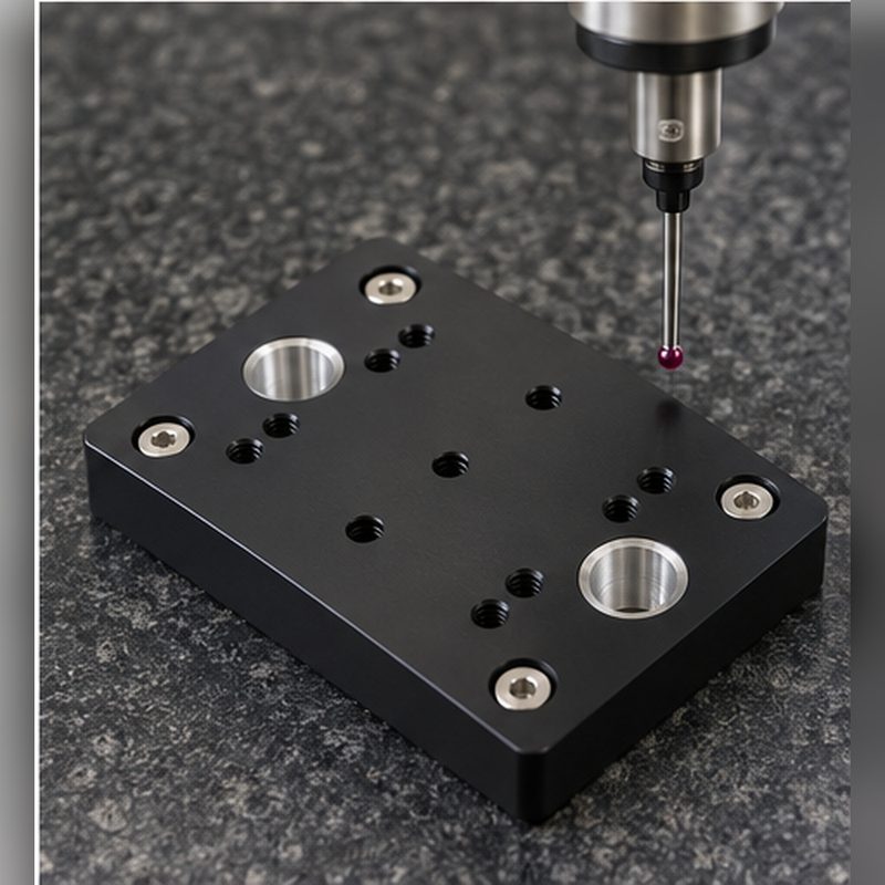
Hole-grid mapping. Dowel bores and tapped holes are mapped on a CMM against the stated datum scheme, and true position is recorded as a reportable value rather than a visual check.
Flatness verification. Tooling-face flatness is confirmed after finishing, since the coated surface is the mounting face.
First article inspection. The first plate receives a full FAI record covering critical dimensions, material traceability and finish thickness; later parts are sampled to the agreed level.
Surface finishing
Hardcoat anodize (Type III). Type III coating over the mounting face and contact areas stops aluminium galling under tool changes; thickness is held in the 25–50 µm band and verified on witness areas.
Masked dowel bores. Dowel bores and toleranced pilot features are masked before anodizing, since the coating grows roughly half its thickness per surface.
Deburr and edge break. Every machined edge is broken before coating so no burr sits proud on the mounting face.
Typical application
This class of plate suits automation cells where one arm carries a family of grippers, vacuum tools or sensor heads and must swap between them without re-teaching positions. Low-volume and repeat-build programs are both normal, so the plate is held to one datum scheme and can be re-made without re-teaching positions.
- Robot end-of-arm tooling and quick-change interfaces cycling many times per shift
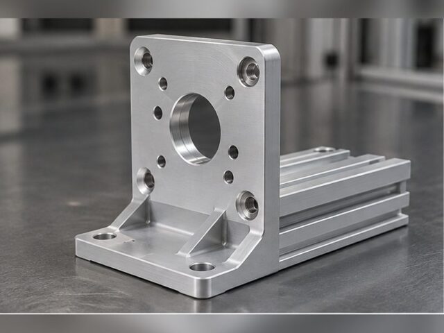
- Gantry and linear-axis carriages where light, stiff mounting protects payload budget
- Sensor and camera plates needing repeatable re-fit after service
Explore the engineering
Have a similar part?
Send the CAD model and drawing with alloy, temper, finish and positional tolerances noted, and Chengdacai’s engineers will review wall thickness, datum strategy, masking and stress control before quoting.
Upload CAD for Quote

 Automation & robotics