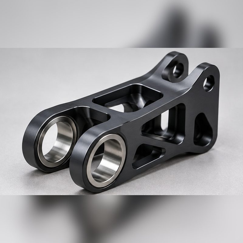
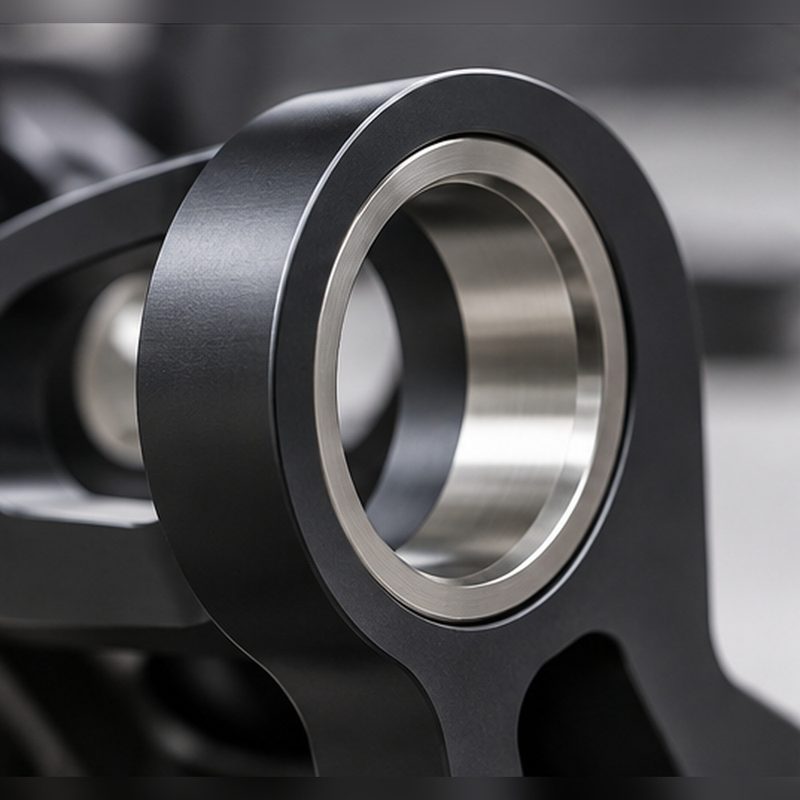
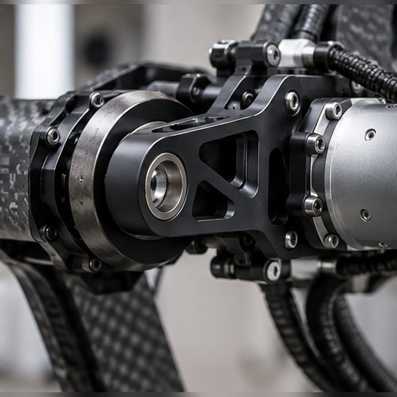
A structural link machined from 7075-T6 aluminum: two bearing bores tied together by a lightweighted web, made for a robotic joint where moving mass and joint clearance both show up at the end-effector.
Project overview
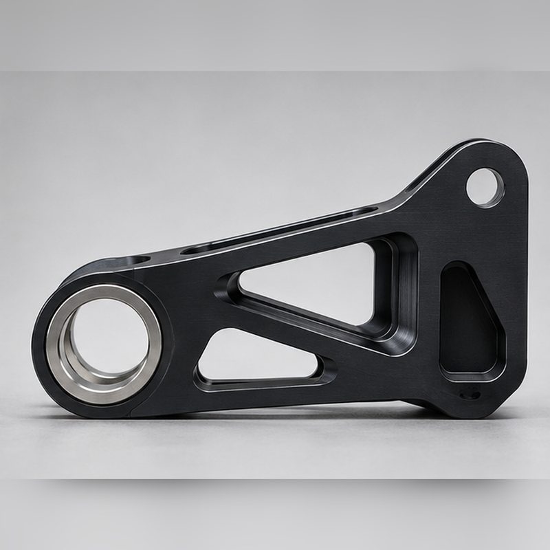
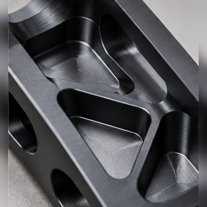
This project is a structural arm bracket that forms one link in a robotic arm — two bearing bores connected by a triangulated, pocketed web. The brief is the classic robotics trade-off: as much stiffness as possible for as little moving mass as possible, with bores accurate enough that joint clearance does not turn into positioning error at the end of the arm.
The bracket is machined from 7075-T6 plate and bar. The load path changes through the thickness, so the material has to be oriented to suit a part that is loaded in more than one direction, and the residual stress that 7075 plate carries is managed rather than avoided. Material is removed symmetrically, the part is allowed to relax, and only then are the bearing bores and datum faces finished. Bores are held as an H7 fit with bore-to-bore position at ±0.02 mm, and hardcoat growth is budgeted into the fit before coating.
A bore that is too tight will not accept the bearing; a bore that is too loose puts clearance in the joint; and a link that warps in the machine defeats both. All sizes, web thicknesses, volumes and lead times here are shown as typical ranges for this class of link rather than one customer’s record — the alloy choice, lightweighting logic and bore control are representative of the robotic structural parts we machine.
Project snapshot
| Item |
Detail |
| Industry |
Robotics / motion control |
| Part type |
Structural arm link / bracket |
| Material |
7075-T6 aluminum plate and bar |
| Finish |
Hardcoat anodize (Type III), bearing bores masked |
| Volume |
Typically 20–100 pieces for prototype and bridge builds, 50–300 pieces in recurring runs |
| Lead time |
Typically 7–12 working days from released drawing to first articles |
Technical specification
The values below describe what is typical for a machined structural link of this size. They are planning ranges for the class of part, not the released drawing of any one program.
| Parameter |
Typical specification |
| Overall size |
Typically 180–260 mm between bore centers, 25–35 mm thick |
| Bearing bore fit |
Typically H7, stated as a fit class rather than a raw ± |
| Bore-to-bore position |
Typically ±0.02 mm |
| Bore-to-datum parallelism |
Typically 0.02 mm |
| Web thickness |
Typically 6–8 mm in the web, thickened to about 12 mm at the bore bosses |
| Pocket floor thickness |
Typically 4–6 mm under lightweighting pockets |
| General tolerance |
Typically ±0.05 mm on machined features unless the drawing states otherwise |
| Hardcoat thickness |
Typically 25–50 µm, budgeted against toleranced bores |
Engineering challenges
Stiffness at minimum moving mass
Every gram on the arm costs cycle time, so pockets are placed to keep material along the load path between the bores and remove it where bending stress is low. The web is triangulated rather than simply thinned, so the link resists bending without relying on added section.
Bearing bores that set joint accuracy
Bore fit and position drive joint clearance, so the bores are finished to an H7 fit and held to ±0.02 mm position after the part has relaxed, in a setup that also cuts the datum faces. Hardcoat growth is compensated on the drawing rather than discovered at assembly.
Distortion in 7075 during heavy removal
Rolled 7075 carries residual stress that releases as material is removed. Roughing is balanced around the neutral axis, a relief pause lets the part move, and finishing takes light, even cuts so the accuracy features are not cut into a part that is still changing shape.
Engineering decision
7075-T6 was selected over 6061-T6 because its yield strength is roughly 1.8 times higher, which lets the web run thin enough to matter on a moving axis while the bore bosses stay rigid; the trade is that 7075 is less forgiving to machine and more prone to movement. The 7075 section is cut from plate rather than formed: because the load path changes through the thickness, the web has to follow the load rather than a constant section. The bore is machined as a fit class rather than a raw diameter so the bearing supplier’s tolerance is honoured, and hardcoat is deliberately budgeted into that fit and masked out of the bore instead of being treated as a postscript — the coating is wear protection for the outside of the link, not something that should be allowed to close up a precision hole.
Manufacturing process
Step 1: Engineering review
Web thickness, bore fits, datum scheme and the hardcoat allowance on toleranced features are reviewed before the plate is cut.
Step 2: Balanced roughing
Material is removed symmetrically from both faces of the 7075-T6 plate to keep stress release even and limit distortion.
Step 3: Stress relief pause
The part is allowed to settle before the accuracy features are cut, so movement happens before, not after, the finish pass.
Step 4: Finish machining of bores and datums
Bearing bores, datum faces and the bore bosses are finished in one setup to an H7 fit and ±0.02 mm position.
Step 5: Masking and hardcoat
Bores and any mating faces that carry a fit are masked, then hardcoat anodize is applied at the specified thickness.
Step 6: Final inspection
Bores are mapped and gauged after coating to confirm position, roundness and fit before the part is released.
Inspection methods
CMM bore mapping
Bore diameters, bore-to-bore position and parallelism are mapped on a CMM against the datum scheme, with the report issued per part number.
First article inspection
A full first article inspection report is produced on the first part, with in-process sampling on the run at the sampling level agreed with the customer.
Post-hardcoat gauge check
Toleranced bores are re-gauged after anodizing to confirm coating growth stayed inside the budget and the H7 fit is still met.
Surface finishing
Hardcoat anodize (Type III)
A typically 25–50 µm wear-resistant layer for a link that sees repeated fastening, clamping and handling on a production floor.
Masked bearing bores
Bores and fit-critical faces are masked so the coating never intrudes on an H7 fit; where coating is allowed, its growth is already in the tolerance budget.
Natural or dyed option
Hardcoat can be left natural or dyed for identification where a program needs to distinguish links, with the same masking rules either way.
Typical application
Structural links and brackets like this form the load-bearing skeleton of robotic arms and motion assemblies, where moving mass costs cycle time and bore clearance turns into end-effector error. 7075 earns its place where stiffness per kilogram, not unit material cost, is the deciding number.
- Robotic arm links, joints and wrist supports
- Gimbal and pivot brackets on motion stages
- Lightweighted mounts where bore alignment drives assembly accuracy
Explore the engineering
Have a similar part?
Upload the CAD model and drawing with the alloy, bore fits and finish callout, and our engineering team reviews the load path, wall thickness, datum scheme and coating allowance before quoting. The review happens before the part reaches a machine, so tolerance and finish problems get answered in the quote rather than in the first article.
Upload CAD for Quote

 Automation & robotics