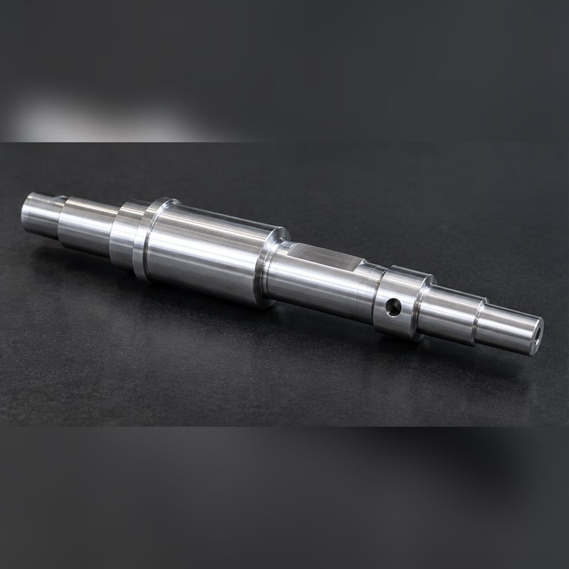
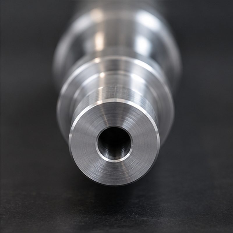
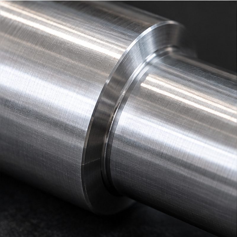
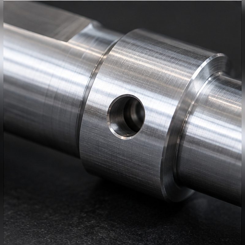
A stepped mill-turn shaft for a rotating assembly: shoulders that seat bearings, threads gauged on assembly, grooves that retain neighbouring components and cross-holes drilled off the turning axis — with every feature referenced back to one common axis.
Project overview
Turning does most of the work, but the part cannot be finished on a lathe alone: diameters, shoulders, threads and retaining grooves turn around the shaft axis, while flats and cross-holes are milled on the same machine so the off-axis details stay tied to the axis turning established. What the customer is really buying is truth to that axis. A bearing seat that runs out does not remain a local defect — it shakes the bearings, the coupling and everything mechanically downstream — so seats and shoulders are held to typically 0.01 mm TIR between seats, with seat diameters to h6 or the fit class named on the drawing.
Two constraints set the routing. A slender 7075 bar deflects under cutting load, so diameters move along the length unless the work is supported and the finishing passes are kept light. And each extra setup re-clamps the axis and adds a little more runout that no later operation can remove, so the off-axis work is done on the same mill-turn platform as the turning. Volume runs from prototype into production, typically 50–500 pieces, and the lengths, diameters and runout values below are typical ranges for this class of turned part.
Project snapshot
| Item |
Detail |
| Industry |
Automation and robotics motion |
| Part type |
Turned shaft with mill-turn features |
| Material |
7075-T6 aluminum bar |
| Finish |
As-machined; clear anodize optional with fit diameters masked |
| Volume |
Prototype through production runs, typically 50–500 pcs |
| Lead time |
Typically 7–12 working days |
Technical specification
The figures below are typical ranges for turned aluminum shafts rather than production data from one customer, and are a starting point for a manufacturability review.
| Parameter |
Typical specification |
| Overall envelope |
Typically 120–180 mm long, 20–30 mm maximum diameter |
| Bearing-seat concentricity |
Typically 0.01 mm TIR between seats |
| Diameter tolerance |
Bearing seats to h6 or the specified fit class |
| Threads |
Gauged threads per drawing |
| Grooves and features |
Retaining grooves, flats and cross-holes (mill-turn) |
| Surface finish |
Typically Ra 0.8 µm on bearing seats |
| Straightness |
Typically 0.02 mm TIR over the shaft length |
| Material condition |
7075-T6 bar, mill certificates retained |
Engineering challenges
Concentricity across features. Each seat, shoulder and thread has to be true to the same axis, and every re-clamp adds a little runout that no later operation can take back out. The job was planned as a small number of setups with the off-axis work done on the mill-turn platform, so stack-up never accumulates in the first place.
Bearing-seat finish and size. A bearing seat has to be both smooth and exactly the right size: leave it rough and the race frets and micro-welds to the aluminium, hold it off size and the bearing either loses its preload or fights the housing. Dedicated finishing passes with fresh tooling hold the seats to typically Ra 0.8 µm and to the specified fit class, and the sizes are gauged rather than assumed from the program.
Slender-part deflection. A long, thin aluminum shaft pushes away from the tool under cutting load, which shows up as a diameter that tapers along its length. Support, light finishing passes and repeat measurement between passes keep the diameters consistent from one shoulder to the other.
Engineering decision
The shaft is turned from 7075-T6 bar, and the stock form matters as much as the material. A rotating component needs a homogeneous, heat-treated section along its whole length; round bar provides that in a form that can be gripped, supported and turned true in one operation. 7075-T6 is chosen over 6061 because a loaded rotating shaft benefits from its considerably higher strength and better fatigue behaviour at the same diameter — the trade-off is that it machines less freely and takes clear anodize less evenly, so non-critical diameters carry the cost and the fit surfaces are protected. Off-axis flats and cross-holes are cut on the mill-turn platform rather than in a second operation, because every re-clamp adds runout that cannot be removed later. Fit surfaces are left as-machined and, where clear anodize is specified for corrosion protection, those diameters are masked so coating growth cannot change a bearing fit.
Manufacturing process
Step 1: Engineering review. Fit classes, concentricity callouts, thread specifications and mill-turn features are confirmed, and the order of turning and milling operations is settled before quoting.
Step 2: CNC turning. The shaft is turned from 7075-T6 bar with separated roughing and finishing passes for diameters, shoulders and grooves, with support where the length-to-diameter ratio demands it.
Step 3: Threading and grooving. Threads are cut and gauged, and retaining grooves are turned to size with radiused roots rather than sharp corners.
Step 4: Mill-turn features. Flats and cross-holes are machined on the same platform so the off-axis features stay referenced to the turning axis instead of a new setup.
Step 5: Deburr and clean. Edges are broken, thread flanks are cleaned and the part is prepared for inspection without disturbing the fit diameters.
Step 6: Optional anodize and final inspection. Clear anodize with masked fit diameters when specified, then concentricity, diameter and thread verification before release.
Inspection methods
Runout and concentricity check. Bearing seats and shoulders are checked for TIR against the shaft axis, typically to 0.01 mm unless the drawing calls for tighter, and the check is repeated along the length rather than at one section.
Thread gauging. Threads are verified with go/no-go gauges against the specified class, so pitch diameter is confirmed rather than assumed from the cutting program.
First article inspection. A full FAI report is produced on the first shaft covering diameters, runout, thread gauging and finish, with sampling on the run set by the program’s own plan.
Surface finishing
As-machined fit surfaces. Bearing seats and the other fit diameters receive no coating, so their size after finishing is the size that was measured at the machine.
Clear anodize on non-fit surfaces. Where corrosion protection is specified, clear anodize is applied to the exposed shaft surfaces while the fit diameters are protected.
Masking of fit diameters. Bearing seats and threaded sections are masked before anodizing so the finish cannot change a fit or the thread class.
Typical application
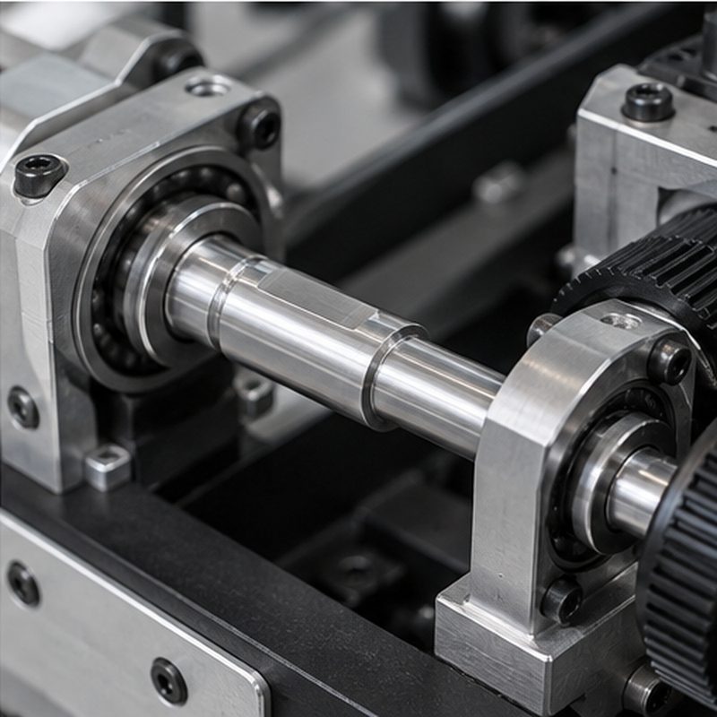
Parts of this family are the rotating member inside automation and robotics assemblies — they run in bearings, carry a pulley or a gear, and step down through shoulders and grooves to position components that travel with them. What is being bought is true rotation, not round diameters: a shaft whose every measurement is in tolerance but which runs out at a seat will still shake the machine it drives.
- Robot joints, actuator and gearbox assemblies with shaft-supported rotating elements.
- Conveyor and indexing mechanisms where a slender aluminum shaft keeps inertia low.
- Prototype through production builds where the same turning and mill-turn routing scales without new fixturing.
Explore the engineering
Have a similar part?
Upload the shaft drawing with its fit classes, concentricity callouts and thread specifications and our engineers will review the turning and mill-turn sequence, the support strategy for the length-to-diameter ratio, and where the tolerance stack should be allocated before quoting.
Upload CAD for Quote

 Automation & robotics