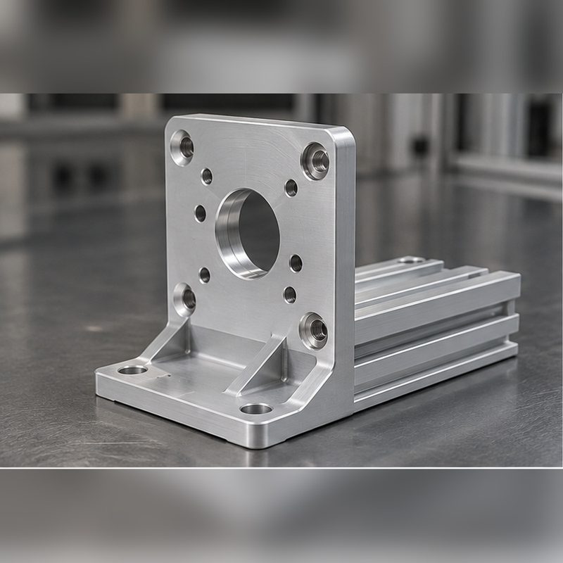
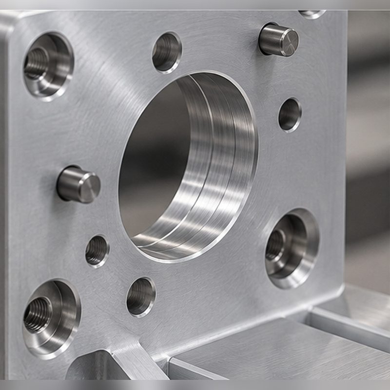
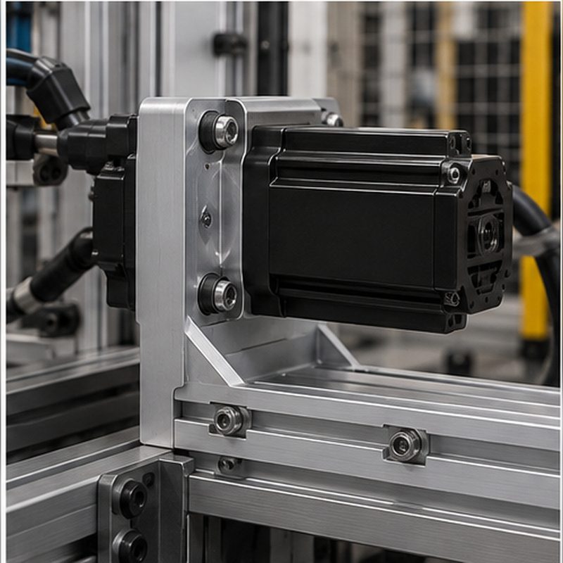
A drive motor has to sit on the machine frame in one exact place, and a stiff couple between the motor and a fabricated frame is worth more than it looks: this mount is a custom 6061-T6 extruded angle, machined from one reference that ties the motor pilot, the fixing bolt pattern and the frame dowels together.
Project overview
Few parts look as easy to make as this one, and few punish a shortcut so consistently. Two relationships decide whether it works. The first is the tie between the pilot bore and the bolt circle: a pilot that sits off-centre pulls the motor off-axis as the bolts come up to torque, and the bearings run preloaded from the day the machine is commissioned. The second is repeatability on the frame — after a motor is pulled for service the mount has to land back in exactly the same place, which clearance holes cannot deliver and dowels can.
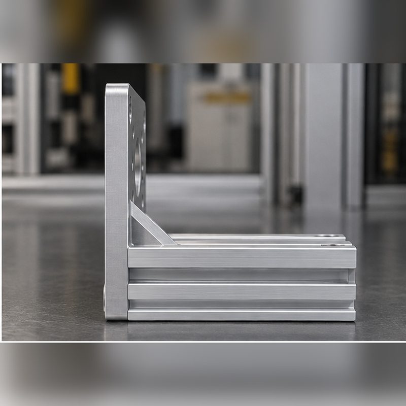
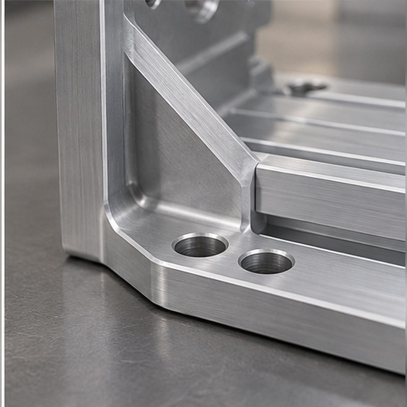
The body is a custom 6061-T6 extruded angle, so the base that lands on the frame and the gusseted wall carrying the motor face come out of one section, and the corner that takes the bending load is continuous metal rather than a welded joint. The mounting face and the motor face are then machined flat and square, and the pilot, the fixing bolt pattern and the dowel bores are then produced off that same reference in one clamping. Volume is recurring, typically 100–1,000 pieces per release, and every figure below is a typical range rather than one customer’s data.
Project snapshot
| Item |
Detail |
| Industry |
Automation equipment |
| Part type |
Motor / gearbox mounting bracket (extruded angle, machined) |
| Material |
6061-T6 aluminum extrusion |
| Finish |
Clear anodize (Type II) with pilot bore and dowel holes masked |
| Volume |
Recurring production, typically 100–1,000 pcs per release |
| Lead time |
Typically 7–12 working days for machining once the profile and first article are approved |
Technical specification
The figures below are typical ranges for machined motor mount brackets rather than production data from one customer, and are a starting point for a manufacturability review.
| Parameter |
Typical specification |
| Overall envelope |
Typically 100–140 mm square, with a 10–15 mm section thickness |
| Pilot bore |
H7 fit to the motor pilot, concentric to the bolt circle |
| Bolt circle position |
Typically ±0.02 mm true position |
| Dowel holes |
H7 reamed for repeatable location |
| Mounting-face flatness |
Typically 0.05 mm across the mounting face |
| As-extruded wall thickness |
Typically 5–8 mm before machining |
| General tolerance |
Typically ±0.05 mm on machined features (ISO 2768-f unless noted) |
| Traceability |
Lot-controlled extrusion with mill certificates retained |
Engineering challenges
Pilot-to-bolt-circle concentricity. If the pilot bore is off the bolt circle, the motor is forced off-axis as the bolts are torqued and the bearings run preloaded. Machining the bore, the bolt pattern and the dowels from one datum in a single setup keeps that relationship as cut instead of depending on two operations lining up.
Repeatable location. A bracket that floats on clearance holes must be re-aligned every time the motor is serviced. Dowel holes reamed to H7 from the same datum as the pilot give the bracket a deterministic position on the frame.
Flat mounting face. A mounting face that is not flat rocks under bolt load, and the motor shifts as the bolts tighten. The face is finished last and held to typically 0.05 mm so the bracket seats on the frame rather than bridging a high spot.
Engineering decision
The bracket is built from a custom extrusion rather than hogged from 6061-T6 plate, and the volume and part shape decide it. At typically 100–1,000 pieces per release the profile die is amortised comfortably, and the extruded angle delivers the base, the wall and the load-carrying corner in one piece with even 5–8 mm walls — where a machined bracket would start from thick plate, remove most of it, and still need the corner tied together. 6061-T6 is specified rather than the easier-extruding 6063-T5 because the bracket clamps a drive motor and carries its reaction torque: the higher yield strength at a bolted joint matters more than the finer extrusion surface a 6063 section would give, and the functional faces are machined all over anyway. All accuracy features — pilot bore, bolt circle and dowels — are cut from a single machined datum rather than measured from the as-extruded surfaces, because extrusion tolerances are generous and should never be part of a location stack. The bracket is then clear anodized for corrosion resistance, with the pilot bore and dowel holes masked so coating growth cannot change the H7 fits.
Manufacturing process
Step 1: Profile and die review. The bracket section is reviewed as a constant cross-section — wall thickness, corner radii, gusset geometry and machining allowance on the faces that will be cut — so the die is cut only once.
Step 2: Extrusion and cut to length. Billets are extruded to the approved section, then cooled, straightened and cut to length with facing allowance for the machining operations that follow.
Step 3: Profile facing and squaring. The mounting face and motor face are machined flat and square to establish the datum every accuracy feature is later referenced to.
Step 4: Bore, bolt circle and dowels. The pilot bore, bolt circle and H7 dowel holes are machined from the common datum in one setup, so their relationship does not depend on a second clamping.
Step 5: Deburr, mask and anodize. Edges are broken and, where needed, chamfered so coating does not bridge a sharp corner; the pilot bore and dowel holes are masked and the parts are clear anodized.
Step 6: Final inspection. The pilot-to-bolt-circle relationship, dowel positions and mounting-face flatness are verified before the bracket is released.
Inspection methods
True-position check. Each hole in the fixing pattern, and every dowel bore, is probed on a CMM and reported against the datum scheme, held to the typical ±0.02 mm true position before sign-off.
Concentricity check. How true the pilot runs to the fixing pattern is measured directly and recorded as its own reported value, because that single number is what the drive alignment depends on.
First article inspection. A full FAI report is produced on the first bracket covering bore, bolt circle, dowels and flatness, with sampling on recurring releases set by the program’s own plan.
Surface finishing
Clear anodize (Type II). Gives the bracket corrosion protection and a uniform industrial appearance while leaving the machined aluminum colour intact.
Masked pilot bore and dowels. The pilot bore and dowel holes are masked so anodic coating growth cannot change an H7 fit or the motor alignment.
Edge break before coating. Edges are broken before anodizing so the coating covers a radius rather than bridging a sharp corner that would later chip.
Typical application
A mount of this kind is where a drive meets a machine frame, and any misalignment between the two does not stay local — it reappears as bearing wear, audible noise and positioning error that is hard to trace back to its source. Building the pilot bore, bolt circle and dowels off one datum turns the bracket into an interface that can be swapped and refitted without realignment.
- Motor, gearbox and actuator mounting on automation equipment frames.
- Applications where a drive is serviced in the field and the mount has to return to the same position.
- Recurring builds of a few hundred to about a thousand units where a profile die is worth amortising.
Explore the engineering
Have a similar part?
Upload the bracket drawing with its motor interface, bolt-circle tolerance and finish notes and our engineers will review the profile section, the datum scheme, the fit callouts and whether an extrusion or a machined plate is the better route at your volume — before quoting, not after.
Upload CAD for Quote

 Automation & robotics