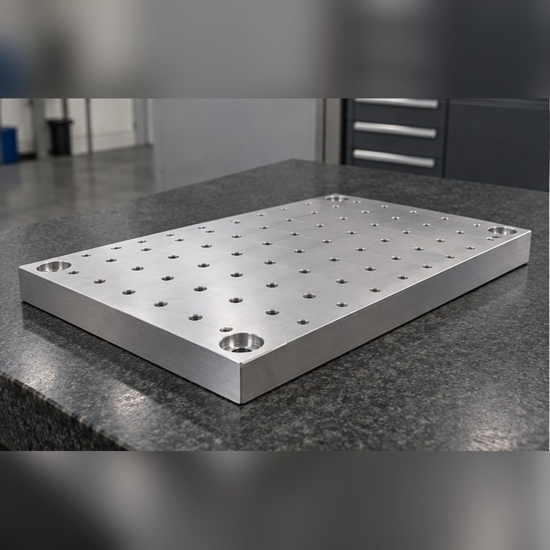
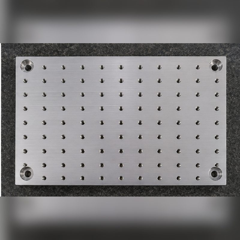
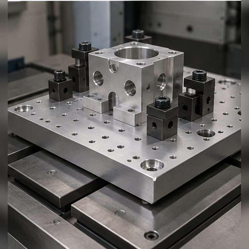
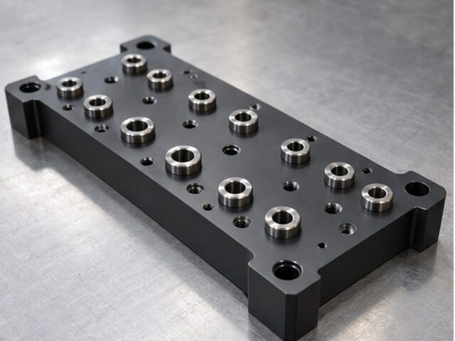
A cast-plate fixture base whose gridded dowel and tapped-hole pattern is cut from one flat datum, so clamps, locating pins and inspection nests drop back into the same position every time the plate is used.
Project overview
The plate is a base tool rather than a deliverable in itself. Clamps, locating pins and metrology nests are fixed to its gridded face, so any error built into that face is inherited by every fixture and every measurement taken above it. Stock is a stress-relieved MIC-6 cast aluminum tooling plate; it is faced and squared, then opened up with an H7 dowel matrix and a tapped-hole pattern, both produced from a single common datum. Working-face flatness is held to typically 0.05 mm and hole-pattern position to typically ±0.02 mm true position, which is what makes a clamp removed and refitted return to the same place.
The material is the engineering story. Cutting a dense hole grid and weight-relief pockets releases residual stress, and ordinary rolled 6061 plate warps as that stress comes out; MIC-6 is stress-relieved at the mill, so it stays flat through heavy machining. Quantities in this case are typical for tooling work — typically one to a few plates per program, not a production run — and every dimension and quantity below is a typical range rather than one customer’s data.
Project snapshot
| Item |
Detail |
| Industry |
Automation and aerospace tooling |
| Part type |
Fixture and inspection base plate |
| Material |
MIC-6 cast aluminum tooling plate |
| Finish |
As-machined datum face; optional hardcoat anodize on wear zones |
| Volume |
Typically one to a few plates per tooling program |
| Lead time |
Typically 7–12 working days per plate set |
Technical specification
The figures below are typical ranges for precision fixture plates rather than production data from one customer, and are a starting point for a manufacturability review.
| Parameter |
Typical specification |
| Plate size |
Typically 300–500 × 200–350 × 20–30 mm |
| Datum-face flatness |
Typically 0.05 mm across the working face |
| Dowel grid |
H7 reamed dowel matrix for repeatable location |
| Tapped-hole matrix |
Gridded tapped holes for modular clamping |
| Hole-pattern position |
Typically ±0.02 mm true position |
| General tolerance |
Typically ±0.05 mm on machined features (ISO 2768-f unless noted) |
| As-machined roughness |
Typically Ra 1.6 µm on the datum face |
| Material condition |
MIC-6 stress-relieved cast plate, mill certificates retained |
Engineering challenges
Flatness after pocketing. A hole grid and weight-relief pockets remove a large share of the plate’s section, and that imbalance is what makes ordinary rolled plate bow. MIC-6 is stress-relieved at the mill, so the plate stays flat through heavy machining, and roughing and finishing passes are separated and sequenced so the face is not closed up while stress is still moving.
Accurate, repeatable grid. A grid earns its cost only if a clamp can be taken off and refitted in the same place months later. Dowel bores were reamed to H7 and the whole matrix was produced in one setup from a single datum, so position comes from the fit instead of from clearance in a drilled hole.
Wear at the contact points. Locating pins and clamp pads bear on the same patches of the face cycle after cycle and eventually burnish or dent them, and a raised burr is enough to spoil the flatness the plate exists to provide. Hardcoat anodizing adds a wear layer to those high-traffic zones, and they are masked so the layer never reaches the working face.
Engineering decision
This is a plate-machined part, and the reason is dimensional rather than commercial. Fixture plate accuracy comes from a single stress-stable billet that can be faced flat and then held flat while the grid is cut. MIC-6 is chosen over rolled 6061 because the cast plate is stress-relieved before machining, so the ±0.02 mm grid and 0.05 mm face survive the pocketing instead of moving afterwards. The working face is left as-machined by design, because any coating applied there would move the very flatness it is there to provide. Hardcoat anodize is therefore restricted to masked wear zones at the clamp and pin contact areas, where a thicker coating can be tolerated. All grid features are cut from a single datum in one setup, which is what makes the position tolerance realistic rather than optimistic.
Manufacturing process
Step 1: Engineering review. Flatness callout, grid tolerance, datum scheme and any wear-zone coating are confirmed, along with the size and quantity of plates, before quoting.
Step 2: Plate facing and squaring. The MIC-6 plate is faced and squared on both sides, taking advantage of its stress-relieved condition and removing the mill surface in controlled passes.
Step 3: Datum face finishing. The working face is finished flat to establish the datum the whole grid is later cut from, and is checked before any pockets are opened.
Step 4: Grid machining. Dowel bores are reamed to H7 and the tapped matrix is cut off the common datum, with weight-relief pockets balanced on both sides of the plate.
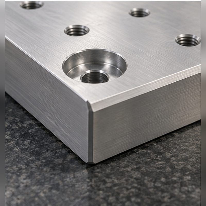
Step 5: Deburr, clean and mask. Edges and bores are broken, the plate is cleaned, and wear zones are masked where an optional hardcoat is specified.
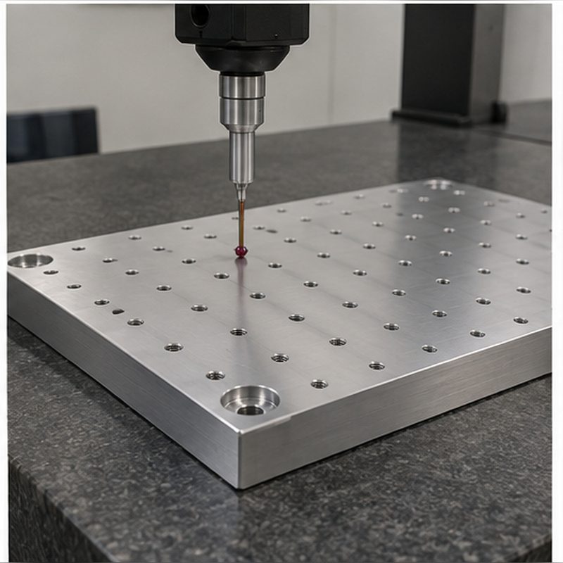
Step 6: Final inspection. Grid position is mapped on a CMM and working-face flatness is verified against the callout before the plate is released.
Inspection methods
Flatness check. Working-face flatness is verified against the typical 0.05 mm callout after machining is complete, since pocketing is what normally disturbs it.
Grid position mapping. Every dowel bore and tapped hole is probed on a CMM and reported against the datum scheme, with the dowel diameter gauged separately so that size and position are each confirmed.
First article inspection. A full FAI report is produced on the plate, with sampling on repeat plates set by the program’s own plan, and mill certificates for the MIC-6 stock are retained.
Surface finishing
As-machined datum face. Nothing is applied to the working face, so its flatness and its nominal dimensions remain exactly as they were cut.
Optional hardcoat on wear zones. Where clamps and pins are cycled heavily, those specific patches can be hardcoat anodized while the remainder of the plate, including the whole working face, is masked and left bare.
Masking before coating. Zones that must remain bare are masked before any anodizing so a fit or a datum is never altered by finish build-up.
Typical application
A plate of this kind is the common reference that a cell’s clamps, pins and metrology fixtures are built from, which is why its accuracy is worth more than its material cost. Cast MIC-6 is the default here because it survives heavy pocketing still flat, where a rolled 6061 plate would move as machining released its residual stress.
- Workholding bases for automation and end-of-arm tooling cells where clamps are repositioned regularly.
- Inspection and metrology nests that need a stable, repeatable datum surface.
- Tooling programs where one to a few plates serve an entire cell, so a stable plate matters far more than a lower unit cost.
Explore the engineering
Have a similar part?
Upload the plate drawing with its flatness callout, grid tolerances and finish notes and our engineers will review the datum scheme, pocket balance and coating plan before quoting — including whether MIC-6 is genuinely needed for your application or whether a standard plate would hold the tolerances you have specified.
Upload CAD for Quote

 Aerospace & tooling