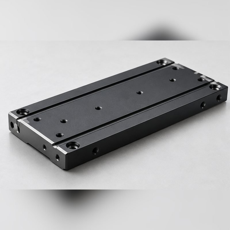
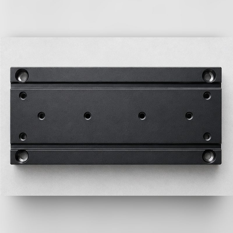
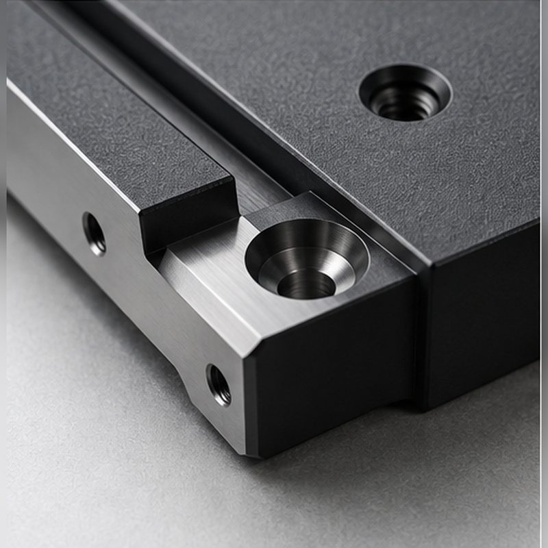
This plate is a sliding wear component in machinery. Geometrically it is simple: a flat plate carrying milled slots and counterbored fixing holes. What makes or breaks it is the coating — Type III hardcoat anodize lets a light, easily machined aluminium plate survive continuous rubbing that would otherwise force a heavier, harder material.
Project overview
The plate carries a working face that runs against a mating surface, milled guide slots that keep travel aligned, and counterbored mounting holes that clamp it to a moving structure. It is also visible on the machine, so appearance matters alongside function — which is why the surface is bead blasted before coating.
The engineering problem is entirely about living with the coating. A hardcoat layer builds outward and inward by about half its thickness on each coated surface, so a bore that measures perfectly before anodizing finishes undersize or over-tight unless that growth is planned for. Here the toleranced bores and fits are masked, coated features are pre-sized for growth, and racking is arranged so the working face builds coating evenly rather than thicker at the contact points. Because the coating changes geometry, the last measurement pass comes after finishing as well as before it: coating thickness on witness areas, and every masked fit measured again so the growth is proven to be inside tolerance.
Plate sizes, coating thicknesses and batch quantities below are typical for wear plates of this class, not one customer’s recorded data.
Project snapshot
| Item |
Detail |
| Industry |
Industrial equipment / automation |
| Part type |
Sliding wear plate for a machine interface |
| Material |
6061-T6 or MIC-6 aluminium, depending on the flatness callout |
| Finish |
Hardcoat anodize (Type III) 25–50 µm, bead blasted |
| Key driver |
Wear life with dimensional control of the coating |
| Volume |
Recurring production, typically 20–200 pcs |
| Lead time |
Typically 7–12 working days including finishing |
Technical specification
Values are shown as typical ranges for this class of part rather than a single customer’s drawing.
| Parameter |
Typical specification |
| Overall envelope |
Typically 200–300 × 120–200 × 12–20 mm |
| Minimum wall thickness |
4–5 mm at slot walls, 6 mm minimum under counterbores |
| General tolerance |
±0.1 mm unless otherwise noted |
| Coating thickness |
Type III hardcoat typically 25–50 µm, with growth budgeted into coated fits |
| Coating hardness |
Type III hardcoat, substantially harder than bare aluminium |
| Sliding-face flatness |
0.05 mm across the working face |
| Masked features |
Toleranced bores and fits masked so coating growth cannot consume them |
| As-machined roughness |
Ra 1.6 µm on the sliding face before coating |
Engineering challenges
Coating growth on toleranced features. Every micrometre of hardcoat changes the part. Bores, counterbores, slots and location features all move if the coating covers the whole surface, so the masking plan is written at quoting and coated features are pre-sized to finish correctly after growth. Getting this wrong is not cosmetic — it turns a usable fit into interference.
Even coating across the working face. A slide plate wears where it rubs, and a coating that builds unevenly leaves soft spots that wear first. Racking position, contact points and masking are arranged so the current reaches the working face uniformly.
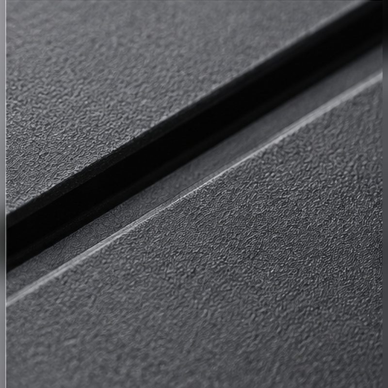
Appearance on a functional surface. The plate is both a wear component and a visible part of the machine, so pre-texture and coating must deliver a uniform result. Bead blasting before hardcoat gives an even matte base, so colour and sheen read consistently.
Engineering decision
The decision on this part is the order of operations, and it exists because the finish changes the dimensions. The route is machining → bead blast → mask → hardcoat → post-coat inspection, and it cannot be rearranged without losing something: blasting after coating damages the hard layer, masking after the fact is impossible, and inspecting only before coating leaves the delivered fit unverified. On a plate this simple, the coating plan is the engineering content.
Material is the second decision, and it turns on the flatness requirement rather than the outline. A plate that must simply be flat, stable after machining and free of internal stress is best made from cast, stress-relieved MIC-6 tooling plate, which machines flat and stays flat. Where the plate must be stronger or carries more load, 6061-T6 is used and stress control comes from the machining sequence — even stock removal, a relief step, finish cuts last. Either way the plate is machined from stock, so there is no forming step for residual stress to hide in.
Manufacturing process
Step 1: Engineering review. Features to be masked are identified, hardcoat growth is budgeted into every coated fit, and the flatness callout confirmed.
Step 2: Blank preparation and machining. The plate is sawn, squared and machined with even stock removal and a stress-relief step to protect flatness.
Step 3: Face and feature finishing. The sliding face is finished flat and to size with allowance for coating growth; slots, counterbores and mounting holes are completed.
Step 4: Bead blasting. A uniform matte pre-texture is applied so the finished plate reads consistently under the functional coating.
Step 5: Masking and hardcoat. Bores, fits and location features are masked, then Type III hardcoat is applied to thickness with racking chosen for even build.
Step 6: Post-coat inspection. Coated dimensions, flatness and coating thickness are re-checked to confirm the growth landed inside tolerance.
Inspection methods
Coating thickness check. Hardcoat thickness is measured on witness areas against the 25–50 µm specification, since the layer determines wear life.
Post-coat dimensional check. Masked fits, coated bores and the sliding face are re-measured after finishing to confirm growth stayed inside tolerance.
First article inspection. The first plate is documented end to end — as-machined and as-coated dimensions, flatness, and finish thickness — with production sampling at the level the program sets.
Surface finishing
Hardcoat anodize (Type III). The defining specification: a hard, low-wear running face, far harder than bare aluminium and applied at a controlled 25–50 µm.
Bead blasting. Applied before coating to give an even matte base, so colour and sheen read consistently on the finished part.
Masked precision features. Bores, counterbores and fits are masked so coating growth never reaches the toleranced dimensions.
Typical application
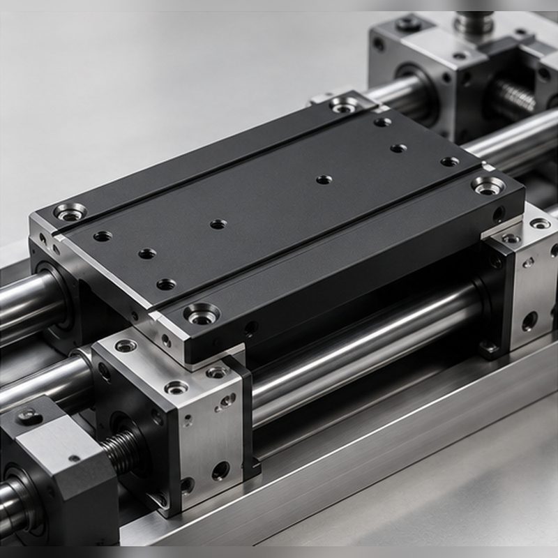
Wear plates like this sit at sliding interfaces in industrial machinery and automation, where bare aluminium would gall and wear through quickly. Type III hardcoat is what makes the aluminium plate viable: it provides the wear resistance of a considerably harder material while keeping the low weight and machinability that make the part economic.
- Linear guides, slide ways and cam tracks running against a mating surface
- Automation equipment needing a replaceable plate to protect costlier structure
- Low-volume and replacement wear parts where a light plate is preferred over steel
Explore the engineering
Have a similar part?
Upload the plate drawing with the alloy, flatness callout, required hardcoat thickness and the features that must stay on size, and Chengdacai will review the masking plan, coating-growth budget and material choice before quoting.
Upload CAD for Quote

 Industrial equipment & controls